
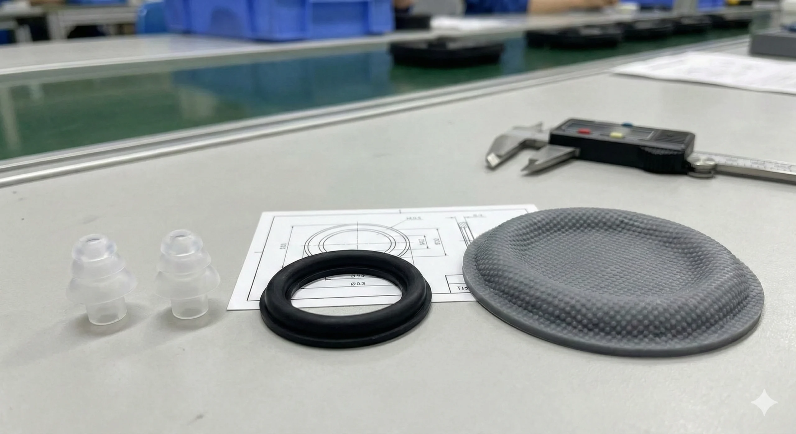
Front Acoustic Gasket
Seals front chamber to prevent sound leakage and maintains acoustic pressure for better bass response

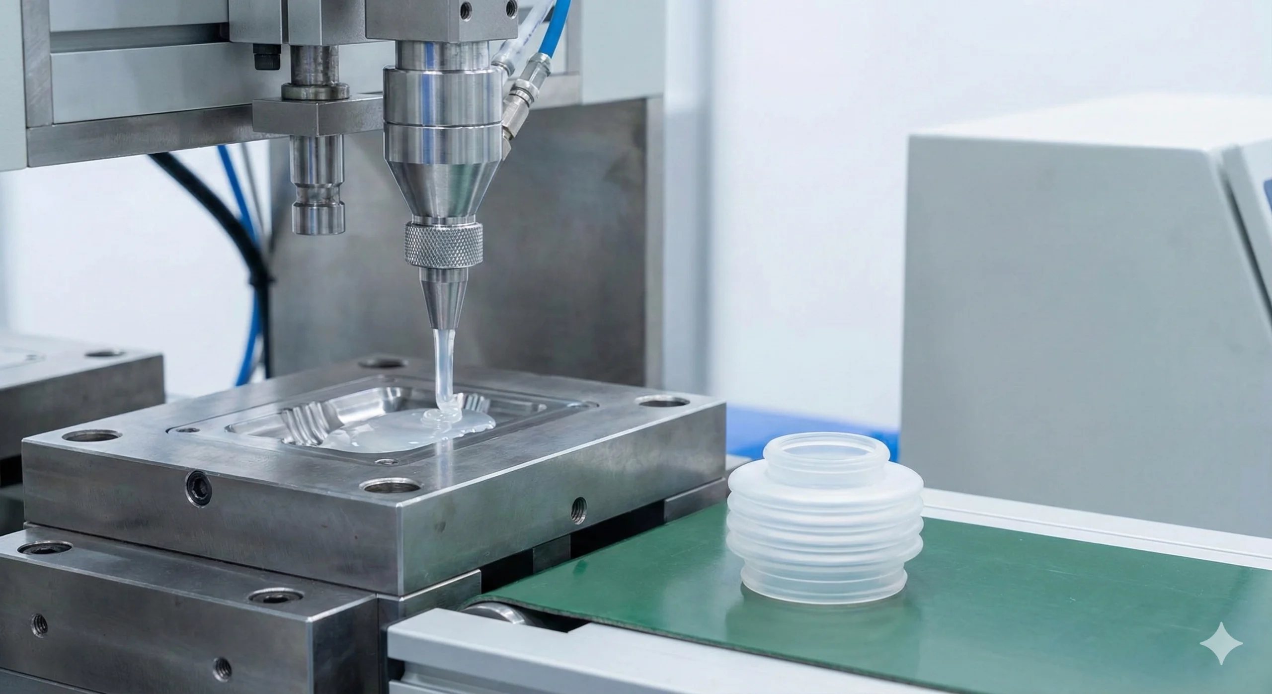
Stop leakage, noise, and IP failures before they reach production. From speaker gaskets to microphone seals, we deliver precision acoustic silicone parts with 24-hour engineering review and mass production consistency.
24-Hour DFM Review
Fast Prototyping
Production Consistency
ISO Certified Quality
Every acoustic failure has a root cause. Understanding these common issues helps you design parts that work right the first time.
Most common complaint
Root Cause
Insufficient compression force or sealing path breaks due to parting line placement on the sealing surface
Our Prevention
DFM review verifies compression zones, parting line location, and sealing path continuity before tooling
Assembly quality issue
Root Cause
Friction between parts, gaps allowing vibration, or rebound force mismatch during operation
Our Prevention
Material selection for low friction coefficient and damping validation during prototype phase
Testing rejection
Root Cause
Flash on sealing surface, tolerance drift affecting compression, or improper waterproof architecture
Our Prevention
Flash control strategy in tooling design plus in-process inspection checkpoints with traceability
PSA failure
Root Cause
Surface contamination, wrong adhesive selection for substrate, or insufficient surface preparation
Our Prevention
Adhesive matching to substrate material plus clean room processing with surface treatment protocols
Fit issues
Root Cause
Geometry mismatch with housing, tolerance stack-up errors, or deformation under compression
Our Prevention
Tolerance analysis during DFM phase and assembly simulation with customer housing models
Long-term seal loss
Root Cause
Material grade mismatch, curing process issues, or compression design exceeding material limits
Our Prevention
Material specification aligned to compression set targets plus aging validation tests per requirement
Dimensional instability
Root Cause
Wall thickness variation, cooling rate differences, or improper ejection forces during demolding
Our Prevention
Uniform wall thickness design guidance and process parameter optimization with cooling control
Environmental damage
Root Cause
UV exposure, temperature cycling, or chemical environment mismatch with material selection
Our Prevention
Environmental condition profiling to match material grade with UV stabilizers or special additives
Barrier failure
Root Cause
Gap design issues in dust barrier structure or mesh opening size mismatch with particle requirements
Our Prevention
Barrier architecture review with mesh specification aligned to IP rating and acoustic transmission needs
Inconsistent quality
Root Cause
Process control gaps, incoming material variation, or insufficient inspection checkpoints
Our Prevention
Multi-point QC system with IQC, IPQC, FQC checks plus statistical process control and lot traceability
Early DFM warnings identify risks before tooling investment
Material and process matching based on actual application risk profile
Multi-checkpoint inspection system with full batch traceability
Every acoustic device has critical seal paths, vibration paths, and dust/water barriers. Understanding where parts go and what they do helps you specify the right solution.
Speaker module showing seal and damping paths
Seals front chamber to prevent sound leakage and maintains acoustic pressure for better bass response
Maintains precise speaker position and absorbs assembly tolerances to prevent rattle during vibration
Decouples speaker from housing to reduce unwanted resonance transfer to device body
Protects speaker membrane from particles and moisture while allowing acoustic transparency
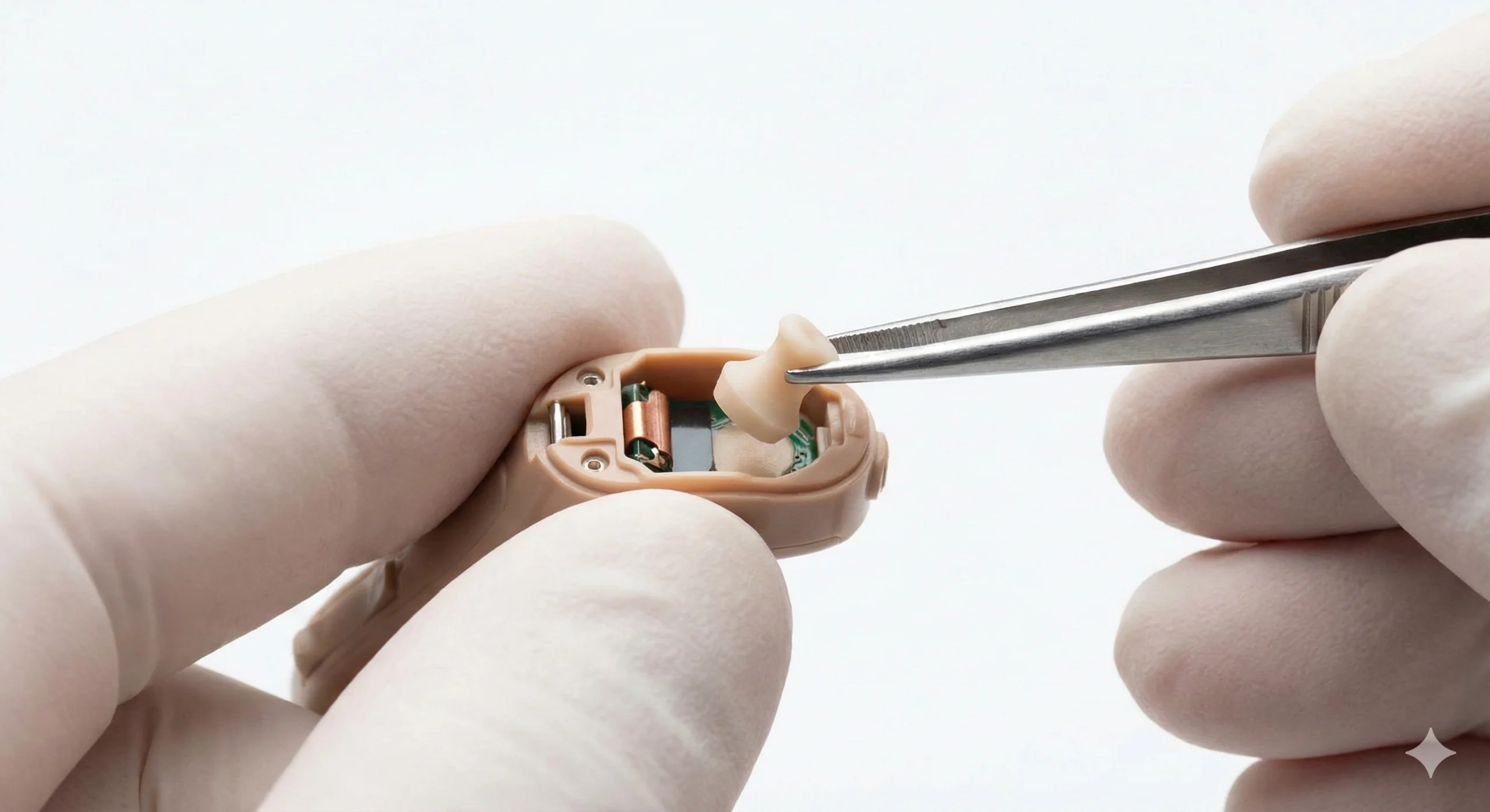
Microphone acoustic path and sealing structure
Creates acoustic isolation between microphone port and housing to prevent sound path interference
Holds waterproof membrane in position while maintaining acoustic transmission and IP rating
Seals dust filter to microphone housing preventing particle ingress without acoustic loss
Provides compression between microphone and PCB while preventing acoustic feedback through structure

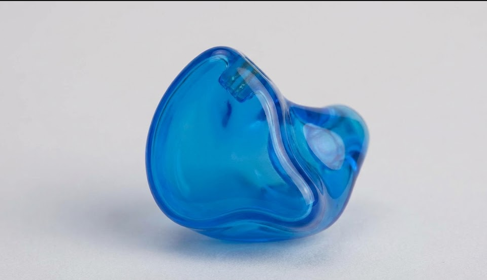
Earbud acoustic chamber and sealing components
Isolates driver chamber from back cavity to maintain acoustic separation and sound quality
Creates comfortable seal in ear canal for passive noise isolation and bass retention
Prevents component movement inside earbud housing during user activity and vibration
Seals pressure equalization vent while maintaining waterproof integrity and acoustic tuning
Need help identifying which parts your device requires?
Get Expert Part RecommendationBrowse by function to quickly locate the silicone parts your acoustic device needs, with material recommendations and common failure modes for each type.
Prevent sound leakage and maintain IP ratings with precision-molded acoustic seals designed for consistent compression.
Common Types
Speaker gaskets, microphone O-rings, enclosure seals, perimeter barriers, waterproof plugs
Eliminate rattle and unwanted resonance with vibration isolators engineered for specific frequency ranges.
Common Types
Vibration isolators, damping pads, shock absorbers, anti-rattle bumpers, isolation feet
Protect sensitive acoustic components from environmental ingress while maintaining acoustic transparency.
Common Types
Protective rings, mesh supports, barrier covers, vent seals, membrane holders
Ensure precise component placement and absorb tolerance stack-up with custom positioning features.
Common Types
Spacers, alignment cushions, positioning rings, assembly guides, tolerance absorbers
Simplify assembly with pressure-sensitive adhesive backing matched to your substrate material.
Common Types
Adhesive-backed gaskets, foam pads with PSA, mounting tapes, sealing strips, composite layers
Integrate metal or plastic inserts with silicone sealing in a single assembly-ready component.
Common Types
Insert-molded gaskets, hybrid seals, metal-backed dampers, multi-material assemblies
We specialize in custom acoustic silicone solutions. Send us your requirements and we'll design the right part for your application.
Request Custom Part DesignDifferent industries have different priorities. We match our acoustic silicone solutions to your specific validation requirements and failure risks.
High-volume production demands consistent aesthetics, tight tolerances, and reliable mass production processes that maintain quality across millions of units.
Key Performance Priorities
Typical Validation Focus
Compact devices require miniature parts with tight tolerance stack-up management, plus resistance to sweat, water, and continuous skin contact.
Key Performance Priorities
Typical Validation Focus
Extreme temperature cycling, long service life requirements, and stringent quality standards demand materials and processes that maintain performance for years.
Key Performance Priorities
Typical Validation Focus
Studio monitors, PA systems, and live sound equipment demand structural stability, zero rattle, and reliable enclosure sealing for premium acoustic performance.
Key Performance Priorities
Typical Validation Focus
We understand the specific validation requirements and failure modes for your device category. Let's discuss your application needs.
Schedule Engineering ConsultationChoose the right material based on your sealing, damping, and assembly requirements. Each material type offers distinct advantages for specific acoustic applications.
For Sealing & Precision
Best For:
Key Benefits:
Typical Hardness:
20A - 80A Shore
For Geometry & Cost
Best For:
Key Benefits:
Typical Hardness:
30A - 70A Shore
For Cushioning & Damping
Best For:
Key Benefits:
Typical Density:
0.3 - 0.6 g/cm³
For Integration
Best For:
Key Benefits:
Typical Configuration:
LSR + PC/PA/Metal
❶ Target Function?
❷ IP Requirement?
❸ Temperature Range?
❹ Assembly Method?
❺ Volume & Cost Target?
❻ Special Requirements?
Send us your application requirements and we'll recommend the optimal material, process, and validation approach tailored to your needs.
Request Material AnalysisSelect the optimal manufacturing process based on geometry complexity, tolerance requirements, cosmetic needs, and cost expectations for your acoustic parts.
Solid Silicone • High Volume • Cost-Effective
Best For
Watch-Outs
How We Control It
Liquid Silicone • Precision • Clean Room
Best For
Watch-Outs
How We Control It
Multi-Material • Integration • Assembly Reduction
Best For
Watch-Outs
How We Control It
Adhesive-Backed • Fast Assembly • 2D Geometry
Best For
Watch-Outs
How We Control It
Send us your drawing and requirements. We'll analyze geometry, tolerance, volume, and cost to recommend the optimal manufacturing process for your acoustic silicone parts.
Get Process RecommendationEvery specification impacts performance. Understanding how hardness, compression, tolerance, and friction affect your acoustic parts prevents costly failures in production.
Why It Matters
Balances sealing force vs assembly ease. Too soft = poor durability, too hard = insufficient conformability to surfaces
Failure Risk
Leakage if too hard, compression set failure if too soft for application loads
How We Control
Durometer testing per ASTM D2240 on every production lot with SPC tracking
Why It Matters
Determines sealing effectiveness. Must be sufficient without over-stressing material or causing permanent set
Failure Risk
Under 15% = leakage risk. Over 40% = permanent deformation and seal loss over time
How We Control
DFM review validates compression zones before tooling. Prototypes tested for assembly force
Why It Matters
Predicts long-term seal retention. High set means eventual leakage over product life cycle
Failure Risk
Seal loosens over time, causing late-life IP failures and customer complaints
How We Control
Aging validation per ASTM D395 at elevated temperature matching application conditions
Why It Matters
Affects assembly fit and seal consistency across production batches and part-to-part variation
Failure Risk
Loose tolerance = batch variation. Tight tolerance = yield loss and cost increase
How We Control
OGP automated inspection plus statistical process control with Cpk tracking
Why It Matters
High friction causes squeaks, rattles, and wear during vibration in acoustic applications
Failure Risk
Audible noise generation during speaker operation or user handling
How We Control
Low-friction material grades available and surface treatment options like powder coating
Why It Matters
Prevents propagation of edge nicks during assembly or use in thin-section designs
Failure Risk
Thin sections tear during installation or vibration cycles leading to seal failure
How We Control
Material selection validation per ASTM D624 Die C with minimum requirements
Send us your current specifications or target requirements. We'll review for potential failure modes and recommend optimal values for your application.
Request Spec AnalysisPractical no-rework guidelines covering sealing surface design, parting line placement, flash control, venting, and assembly tolerance stack-up for acoustic silicone parts.
Parting line flash interrupts the sealing path causing leakage. Position parting line at least 2mm away from critical sealing surfaces or place it perpendicular to the seal direction.
Without compression stops, assembly force variation causes inconsistent sealing. Design hard stops in the housing to control exact compression percentage between 20-35% for most applications.
Flash is inevitable in silicone molding. Control it through three layers: design geometry that minimizes flash impact, precision tooling with tight shut-off, and inspection criteria that catch excessive flash before assembly.
Trapped air creates voids that weaken the part and create leak paths. Design venting channels in the mold at the last-fill locations and thin sections where air naturally collects.
Silicone's flexibility allows zero draft in many cases, but deep ribs or thin walls need 2-5° draft to prevent drag marks or tearing during ejection. Balance draft with dimensional accuracy needs.
Silicone parts must accommodate tolerance stack-up from plastic housing, metal frames, and assembly process variation. Design sufficient compression range (±0.2-0.3mm) to absorb these variations.
Large thickness variation causes differential curing and cooling rates, leading to warpage and internal stresses. Maintain wall thickness within ±30% of nominal where possible.
Adhesive-backed parts need alignment features to prevent misplacement during assembly. Add tabs, notches, or asymmetric shapes that key into housing features for fool-proof installation.
Interfaces where cables or connectors penetrate the housing are high-risk leak points. Design multi-stage sealing with both static and dynamic compression zones, plus overmold around cables where possible.
Sharp internal corners create stress concentration points that can tear during compression or vibration. Use minimum R0.5mm radius on all internal corners, R1.0mm preferred for high-stress areas.
Mold surface finish transfers to the part. Specify texture requirements clearly - high polish (SPI A2) for cosmetic surfaces, medium texture (SPI B2-B3) for gripping surfaces, and no texture on sealing surfaces.
Over-tolerancing increases inspection cost and yield loss without benefit. Specify tight tolerances (±0.05mm) only on critical dimensions like seal contact width. Use standard tolerances (±0.15-0.20mm) elsewhere.
Clear roadmap showing what you send, what we deliver, and how fast you can move from initial quote to production-ready acoustic silicone parts.
2D PDF, DWG, or 3D STEP/STL files with dimensions and tolerances
Sealing/damping/IP rating requirements and key performance targets
How it assembles, compression method, and mating surface details
Prototype quantity, pilot run, and annual production volume estimates
Operating temperature range, UV/chemical exposure, service life needs
Engineering analysis with manufacturability notes and recommended changes
Optimal material grade and manufacturing process for your requirements
Transparent pricing: tooling cost, part cost, and key cost drivers explained
Detailed schedule from tooling to first samples with milestone dates
Testing and inspection approach aligned to your quality requirements
Quote & DFM
1-2 Days
Tooling
3-4 Weeks
Prototypes
1 Week
Pilot Run
2 Weeks
Mass Production
Ongoing
Upload your drawing and requirements now. Get your free DFM review and quote within 24 hours, with prototype samples in as fast as 4-5 weeks.
Upload Drawing & Get StartedMulti-point inspection system with full lot traceability ensures every production batch matches the quality you validated in prototypes. From incoming materials to final shipment, quality is built in at every step.
Complete quality record with visual, dimensional, and functional test results per your specification
Critical dimensions measured with calibrated tools, documented with actual values vs tolerances
Full traceability to raw material batch, production date, operator, and inspection records
Structured corrective action report for any non-conformance with root cause and prevention plan
Ask us about our defect handling process, containment procedures, or request sample inspection reports from past projects.
Request Quality DocumentationWe map every potential failure risk to specific validation tests. From IP rating verification to long-term aging, our testing capability ensures your acoustic parts meet reliability requirements.
Air/water tightness testing per IEC 60529, pressure decay validation, immersion testing as required
Friction coefficient measurement, abrasion resistance testing, vibration testing at application frequency
Compression set testing per ASTM D395 Method B at elevated temperature matching service conditions
90° and 180° peel strength testing per ASTM D3330, adhesion to actual substrate material validation
Temperature cycling, humidity aging, UV exposure testing, thermal shock per application environment
OGP automated inspection, CMM measurement, statistical process control with Cp/Cpk tracking
We can align our testing plan with your validation requirements and standards. Share your test specifications and we'll propose a prototype plan that delivers test-ready samples.
Request Validation PlanEnd-to-end in-house capability from tooling design to final assembly ensures faster iterations, better quality control, and scalable mass production without outsourcing critical steps.
15+
Molding Machines
50-300T
Press Capacity Range
3-7 Days
Typical Tooling Lead
100K+
Monthly Parts Capacity
24/7
Production Shifts Available
5000㎡
Production Floor Space
Our in-house capabilities mean faster response, better control, and scalable production from prototype to millions of parts. Let's discuss your volume requirements.
Schedule Factory TourReal engineering problems solved through material selection, design optimization, and process control. See how we've helped customers fix acoustic failures and improve production yield.
High-volume smart speaker experiencing inconsistent bass response due to air leakage at gasket interface, affecting customer satisfaction scores.
Root Cause
Parting line positioned on sealing surface creating micro-gaps. Material hardness too high (60A) preventing conformability to plastic housing variation.
Solution
Redesigned parting line 3mm away from seal. Changed to 40A hardness material with raised sealing rib for better contact pressure distribution.
Verification
Pressure decay testing at 50Pa for 60 seconds. Acoustic frequency response measurement confirming bass restoration.
Earbuds passing prototype IP testing but failing in mass production, causing costly rework and delayed shipments to retail channels.
Root Cause
Flash on O-ring sealing surface from compression molding process. Batch-to-batch dimensional variation exceeding ±0.15mm tolerance stack-up budget.
Solution
Converted to LSR injection molding for flash elimination. Tightened critical dimension tolerance to ±0.05mm with in-process SPC monitoring.
Verification
IPX4 water spray testing per IEC 60529. 100% air leak testing in production with go/no-go criteria at 100Pa.
Receiver vibration gasket generating audible squeak noise during phone calls, resulting in customer complaints and warranty returns.
Root Cause
High friction coefficient between silicone gasket and metal speaker frame. Vibration at receiver frequency (1-3kHz) causing stick-slip friction noise.
Solution
Changed to low-friction LSR material grade with reduced coefficient. Added powder coating treatment on contact surface to minimize stick-slip.
Verification
Vibration testing at receiver operating frequency. Noise level measurement in anechoic chamber confirming elimination.
Acoustic seal causing assembly interference during automated installation, requiring manual rework and slowing production line throughput.
Root Cause
Gasket geometry creating high insertion force exceeding robotic assembly capability. Tolerance stack-up not accounting for housing deformation under compression.
Solution
Redesigned with tapered lead-in geometry for easier insertion. Reduced initial compression from 35% to 25% while maintaining seal effectiveness.
Verification
Insertion force measurement confirming <15N target. Automated assembly trials with 100-unit validation run.
24-48 hour response with preliminary root cause analysis and recommended solution approach
Data-driven problem solving using dimensional analysis, material testing, and process validation
Rapid prototype turnaround (5-7 days) for design iterations and validation testing
Verification testing aligned to your quality standards with documented test reports
Send us your problem description, failure symptoms, and current design. We'll analyze and propose a solution approach within 48 hours.
Get Engineering Support