To design for the LSR injection molding process, you must prioritize uniform wall thickness, account for high material shrinkage, and utilize the material’s natural elasticity to simplify complex part ejection. This guide provides a detailed analysis of how to optimize product performance and manufacturing efficiency through specialized liquid silicone rubber (LSR) design and silicone injection molding.
Engineers often face high scrap rates and inconsistent part dimensions when using traditional compression molding for complex silicone designs. These delays in production and quality failures can derail product launches in regulated industries like medical or automotive. Liquid Silicone Rubber (LSR) injection molding provides a high-precision, automated alternative that ensures repeatable quality and complex geometry.
1. What Is the Liquid Silicone Injection Molding Process?
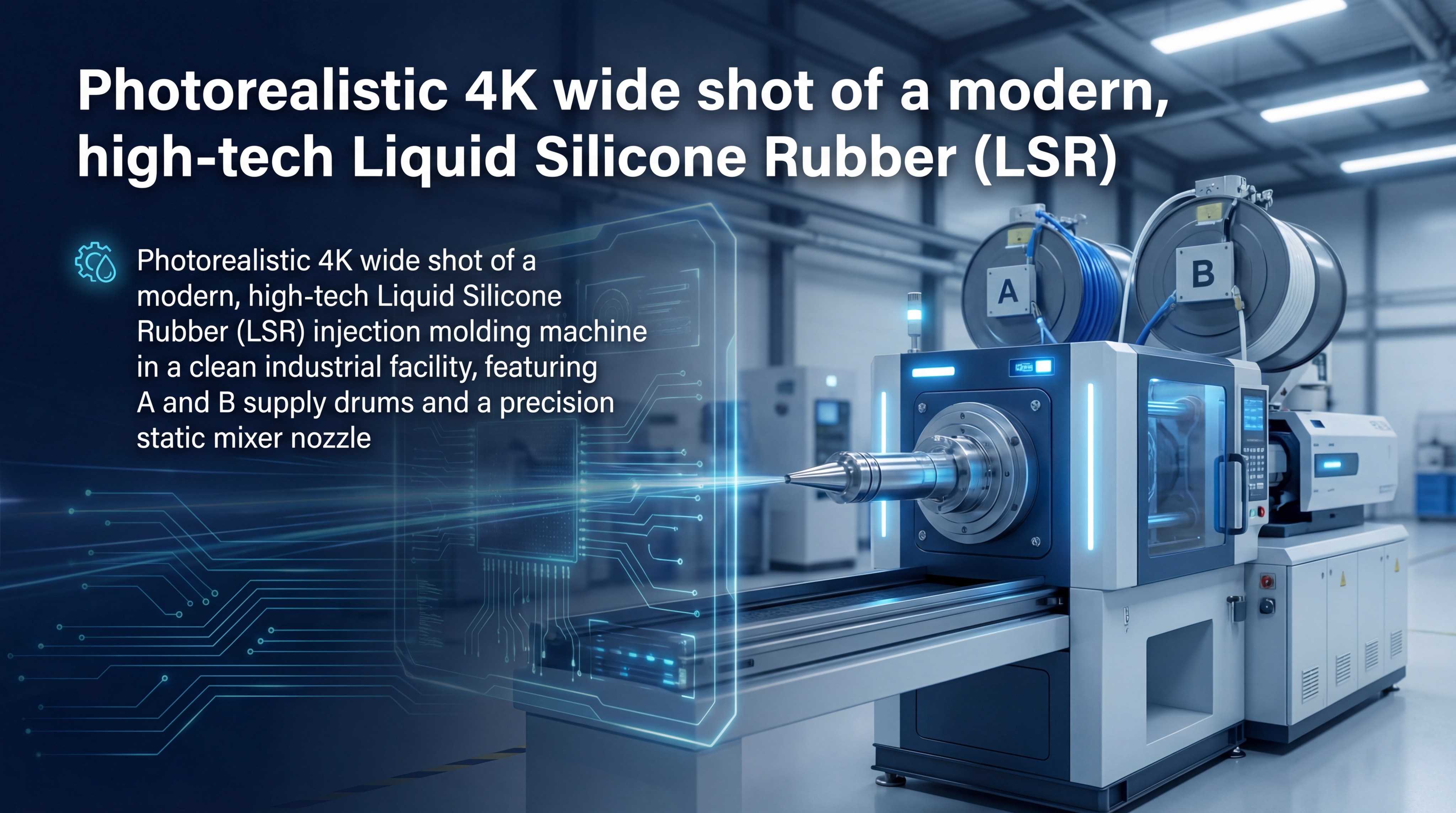
The liquid silicone injection molding process is a high-precision manufacturing method where two-part liquid components are mixed and heat-cured within a mold. This highly automated silicone injection molding system uses closed-loop controls to ensure that the chemical ratio remains perfectly balanced throughout the run. You will find that this consistency is critical for parts requiring tight tolerances.
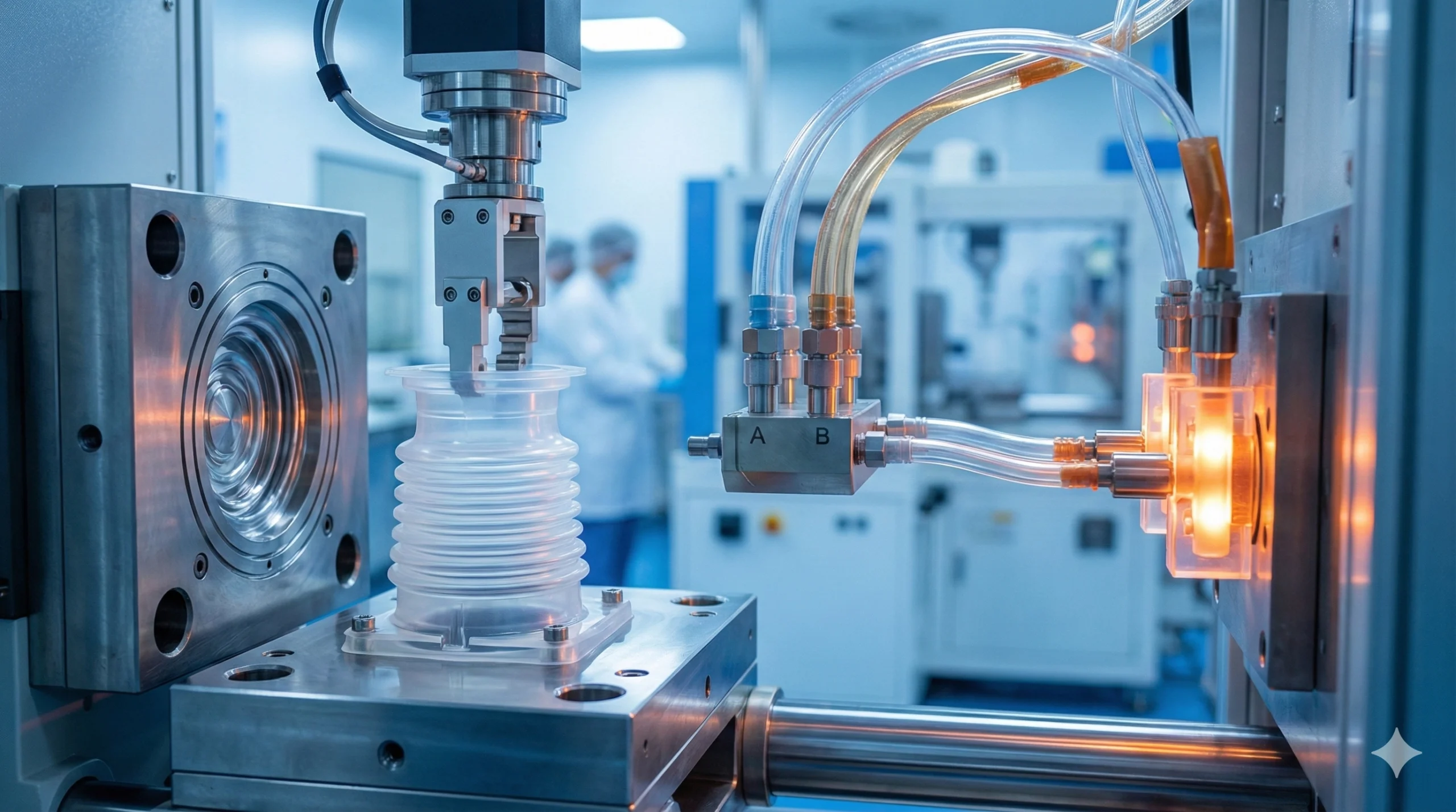
The Mechanics of A and B Component Mixing
The process begins with two separate containers of liquid silicone, typically labeled as Part A and Part B. A metering unit pumps these components into a static mixer at a precise 1:1 ratio.
Think about it this way:
The static mixer acts as the heart of the system, ensuring the catalyst and base material are homogenous before reaching the nozzle.
- Supply drums (Part A & B)
- Hydraulic or electric metering pumps
- Static mixing tube
- Water-cooled injection nozzle
How Vulcanization Differs from Thermoplastic Cooling
Unlike thermoplastics that melt when heated and harden when cooled, LSR is a thermoset material that requires heat to cure. The mold is kept at a high temperature to trigger the chemical cross-linking process known as vulcanization. Once the material sets, it cannot be remelted, making it ideal for high-heat applications.
| Feature | LSR Injection Molding | Thermoplastic Injection |
|---|---|---|
| Material State | Liquid (Cold) | Solid Pellets (Heated) |
| Mold Temperature | Heated (Curing) | Chilled (Hardening) |
| Chemical Change | Irreversible Cross-linking | Reversible Phase Change |
| Cycle Logic | Cure time is primary | Cooling time is primary |
The fundamental difference lies in the thermal energy management, where heat serves as the catalyst for structural solidification rather than a hindrance.
Key Takeaway: LSR is a thermoset process where heat cures the material, unlike plastics which cool to harden.
2. Why Choose LSR Over Traditional Compression Molding?
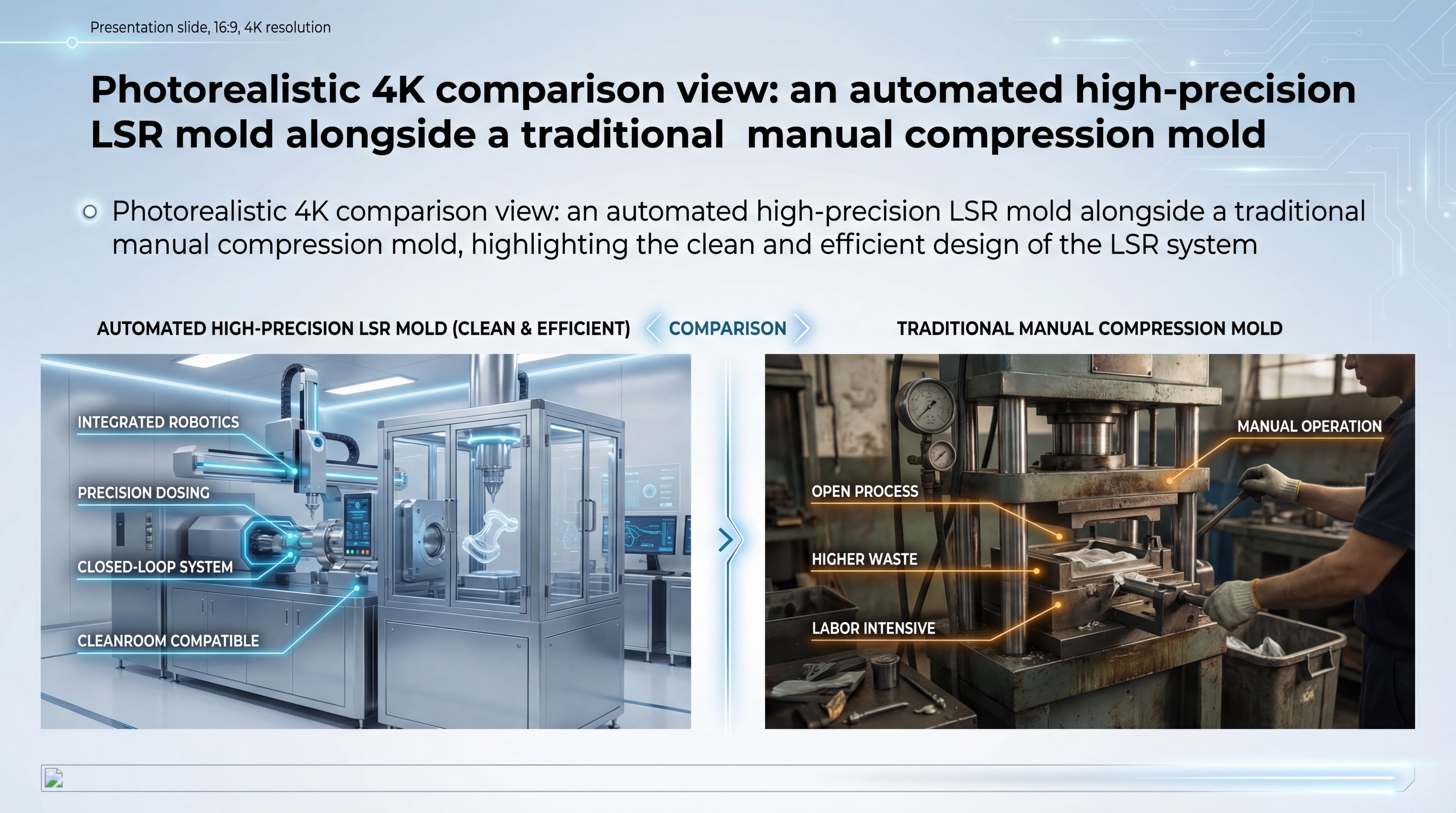
You should choose LSR over compression molding when your project requires high-volume throughput, automated production, and minimal material waste. The transition to a silicone injection molding setup allows for significantly faster cycle times and reduced labor costs. While the initial tooling cost is higher, the per-unit price drops dramatically at scale.
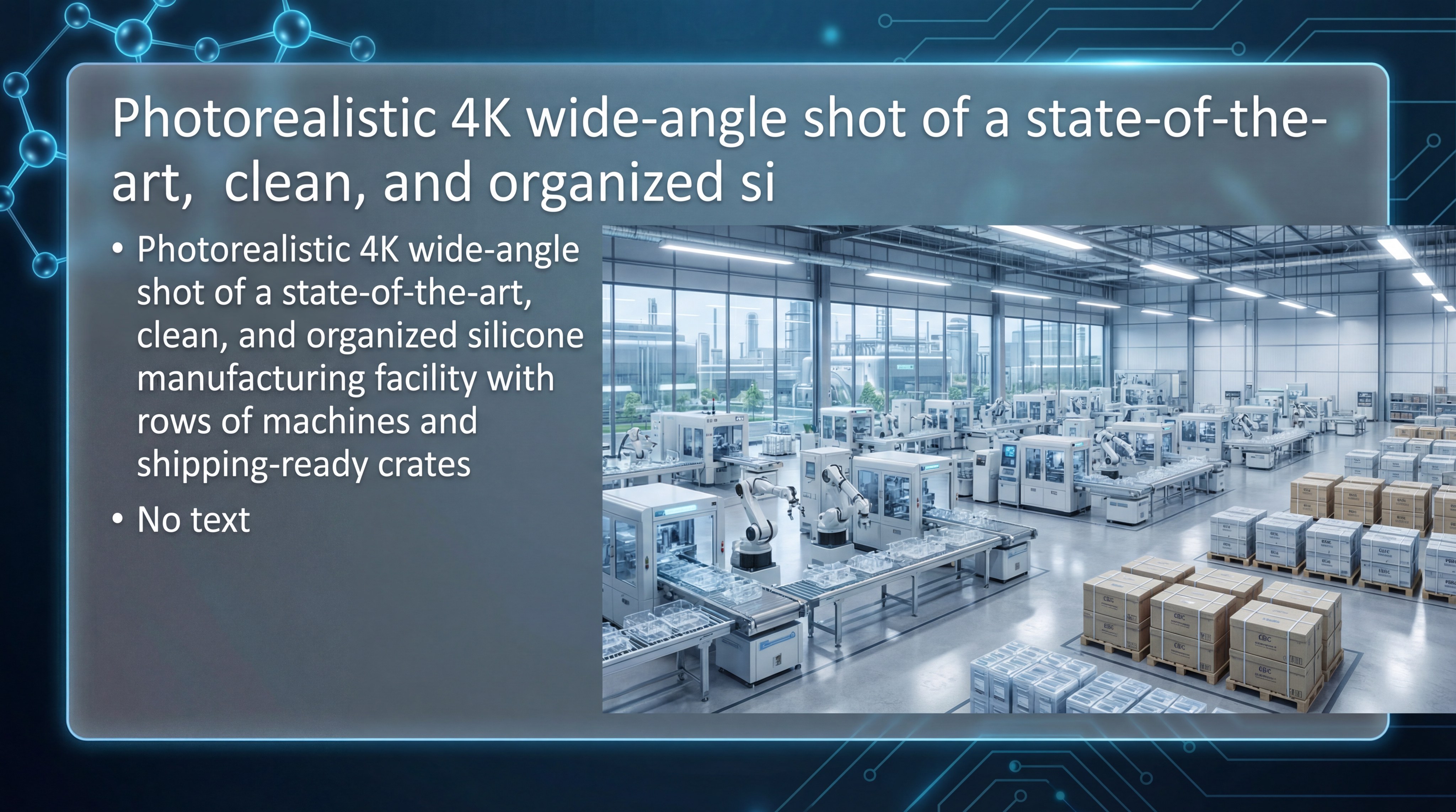
Efficiency Gains in High-Volume Production
Automation is the primary driver of efficiency in modern silicone manufacturing. Because the LSR process is fully enclosed, you can run production 24/7 with minimal human intervention.
Here is the kicker:
LSR cycle times are often measured in seconds rather than the minutes required for traditional compression press cycles.
- Reduced flash and secondary trimming
- Shorter curing cycles
- Lower operator labor requirements
- Stable batch-to-batch repeatability
Precision and Flash Control Advantages
Precision tooling in injection molding prevents the material from escaping the cavity, which is a common issue in open-compression molds. This ensures that your parts maintain a “flash-free” finish straight out of the tool. You can achieve tolerances that are simply impossible with manual loading techniques.
| Metric | LSR Injection | Compression Molding |
|---|---|---|
| Waste Level | Very Low | High |
| Labor Cost | Minimal (Automated) | High (Manual) |
| Precision | +/- 0.05mm | +/- 0.20mm |
| Volume Suitability | High to Mass | Low to Medium |
The shift from manual placement to automated injection represents the most significant leap in silicone quality control available today.
Key Takeaway: For high-volume, high-precision parts, the silicone injection molding process offers lower per-unit costs despite higher tooling investment.
3. Which Material Grade Suits Your Specific Application?
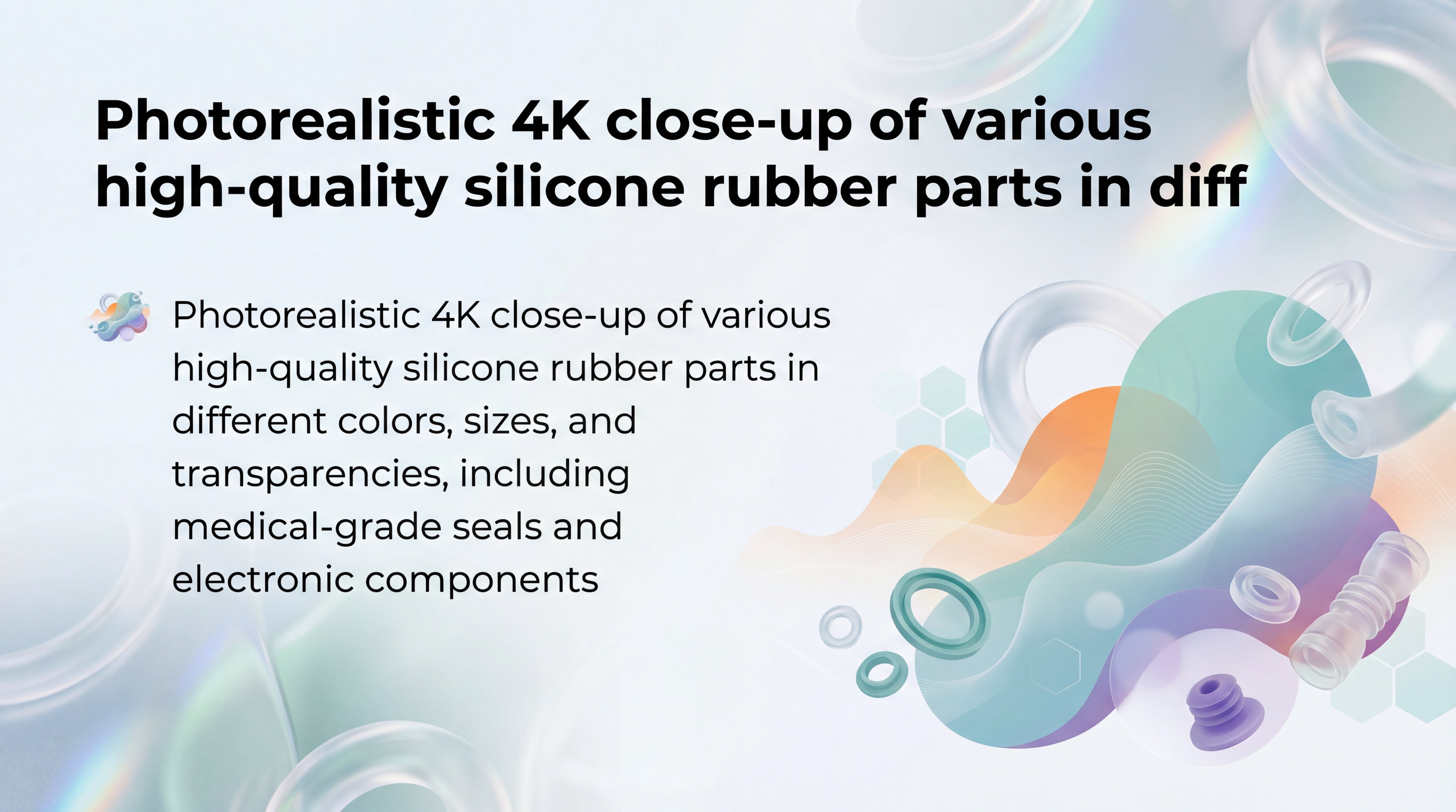
Selecting the right material grade involves balancing physical properties like durometer, transparency, and chemical resistance for your specific environment. In the realm of silicone injection molding, you can choose from specialized formulations that are optimized for biocompatibility or extreme temperature exposure. Your choice directly dictates the mold design and cooling requirements.
Navigating Medical-Grade and FDA Compliance
For healthcare applications, medical-grade LSR is essential due to its high purity and resistance to bacterial growth. These materials are tested for biocompatibility and are often used in medical silicone rubber products like seals and valves.
But wait, there’s more:
LSR can withstand rigorous sterilization methods, including autoclaving and gamma radiation, without losing its mechanical integrity.
- Class VI Biocompatibility
- High-clarity “optically clear” grades
- Odorless and tasteless formulations
- Low volatile content for sensitive electronics
Specialty Grades for Automotive and Electronics
Automotive components require high oil and fuel resistance, necessitating specialized fluorosilicone or oil-bleeding LSR grades. Electronic applications often benefit from flame-retardant (UL 94-V0) or thermally conductive materials to protect delicate circuits. You must ensure the selected grade matches the specific stress profile of your end-use application.
| Property | Medical Grade | Automotive Grade |
|---|---|---|
| Hardness (Shore A) | 10 – 80 | 30 – 70 |
| Clarity | Transparent to Opaque | Mostly Opaque |
| Special Feature | Bio-inert | Fuel/Oil Resistance |
| Compliance | ISO 10993 / FDA | IATF 16949 Standards |
Selecting a grade with the correct durometer ensures the part functions as intended while remaining easy to demold during production.
Key Takeaway: Material selection must account for durometer, sterilization needs, and environmental exposure.
4. How Do You Optimize Wall Thickness and Rib Design?
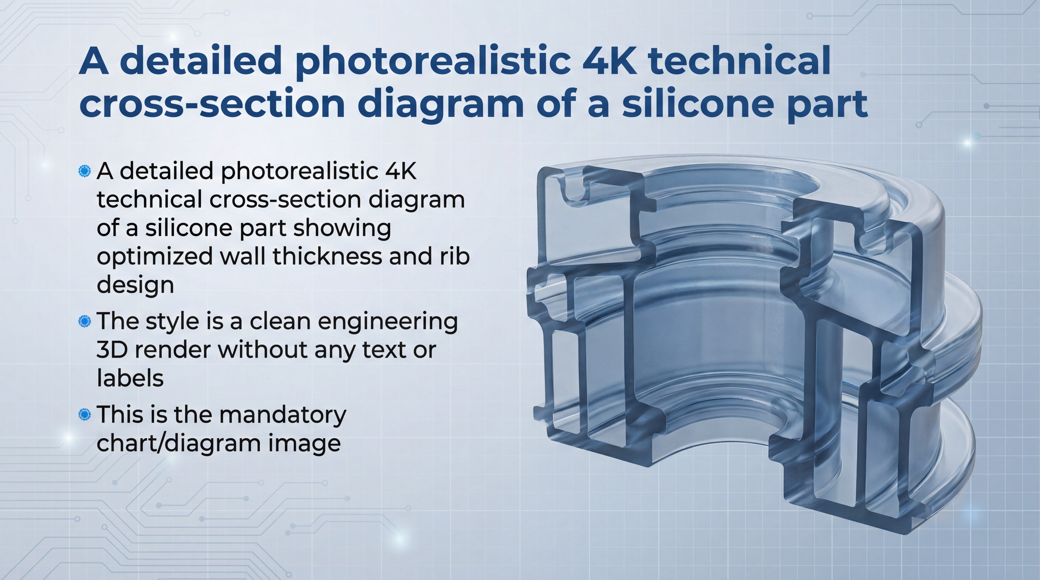
Optimizing wall thickness requires maintaining a uniform cross-section to prevent air entrapment and ensure a consistent cure throughout the part. During the silicone injection molding process, variations in thickness can cause uneven heating and lead to internal voids or surface defects. You should aim for a design that allows the liquid material to flow smoothly into all areas of the cavity.
Preventing Porosity with Uniform Wall Sections
LSR flows like a liquid but cures from the outside in, meaning thick sections may take much longer to stabilize. Keeping walls between 0.25mm and 10mm helps maintain a fast, predictable production cycle.
You might be wondering:
How do I handle designs that require different thicknesses without causing failures?
- Use gradual transitions between thick and thin areas
- Implement “coring out” for bulky sections
- Maintain a minimum wall of 0.25mm for flow
- Avoid sharp 90-degree corners to reduce stress
Structural Integrity Through Effective Rib Ratios
Ribs provide strength and stiffness without adding excessive bulk that would slow down the curing process. A well-designed rib should generally be 0.5 to 1.0 times the thickness of the adjoining wall to maintain structural balance. You must ensure that the base of the rib has a generous radius to facilitate material flow and part removal.
| Design Element | Recommendation | Maximum |
|---|---|---|
| Wall Thickness | 1.5mm – 3.0mm | 10.0mm |
| Min Wall | 0.25mm | N/A |
| Rib Ratio | 0.6x Wall Thickness | 1.0x Wall Thickness |
| Draft Angle | 0 to 2 degrees | 5 degrees |
Consistent geometry is the most effective way to eliminate sink marks and ensure your parts meet high aesthetic standards.
Key Takeaway: Consistent wall thickness is the primary defense against sink marks and internal voids in LSR parts.
5. Can You Manage Complex Geometries and Undercuts?
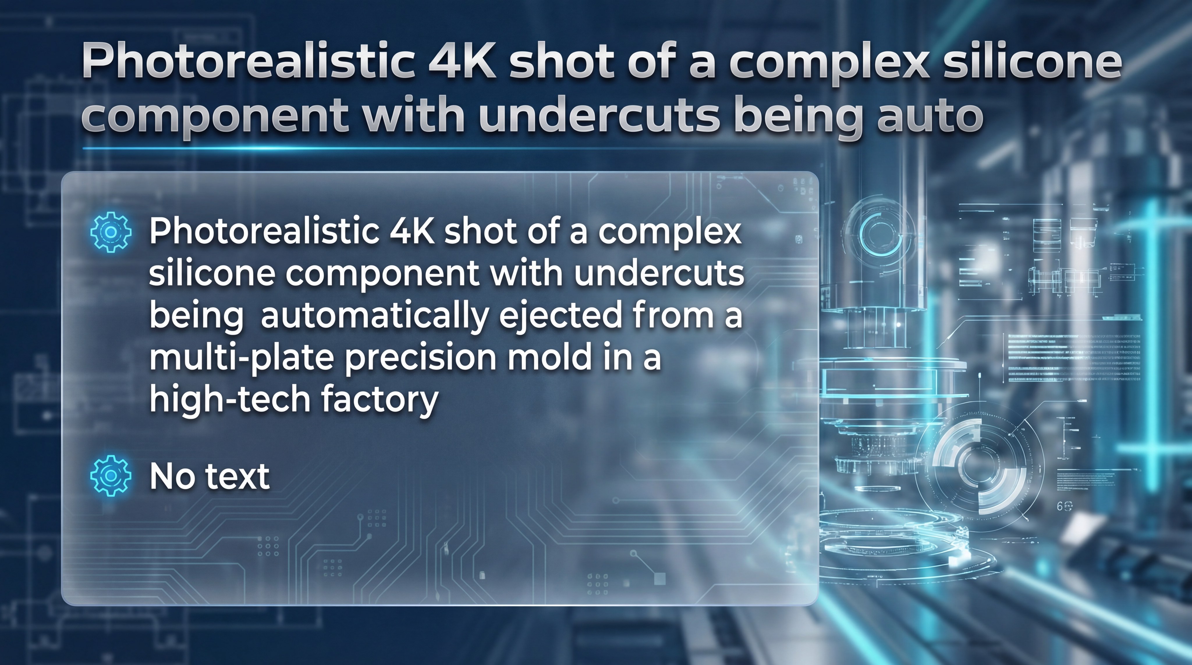
You can manage complex geometries and undercuts far more easily with LSR than with rigid plastics due to the material’s incredible elongation and flexibility. In silicone injection molding, parts can often be “hand-peeled” or blown off the mold core, even if they possess deep undercuts. This flexibility allows for the creation of intricate internal features without needing complex, expensive side-actions in the tool.
Leveraging LSR Elasticity for Part Ejection
Standard LSR can often stretch up to 400% or more during the ejection phase without permanent deformation. This means you can design features like internal threads or barbs that would traditionally require unscrewing mechanisms.
It gets even better:
Using compressed air or mechanical strippers can automate the removal of these complex parts, keeping cycle times low.
- Bellows and convoluted shapes
- Internal seals and gasket grooves
- Overhanging lips for snap-fits
- Complex silicone overmolding parts
Integrated Solutions with Silicone Overmolding
Overmolding allows you to bond LSR directly onto plastic or metal substrates to create a single, multi-material component. This process eliminates the need for adhesives and provides a superior mechanical bond that is waterproof and durable. You should consider this for ergonomic grips, buttons, or integrated sealing surfaces.
| Feature Type | Viability in LSR | Ejection Method |
|---|---|---|
| Minor Undercut | High | Direct Pull |
| Deep Bellows | High | Air Assist |
| Internal Thread | Medium | Collapse/Pull |
| Rigid Overmold | High | Robotic Pick |
The material’s ability to deform and return to its original shape allows for design freedom that is unique to the silicone industry.
Key Takeaway: Silicone’s high elongation allows for demolding undercuts that would be impossible with rigid plastics.
6. What Are the Critical Tooling and Gating Requirements?
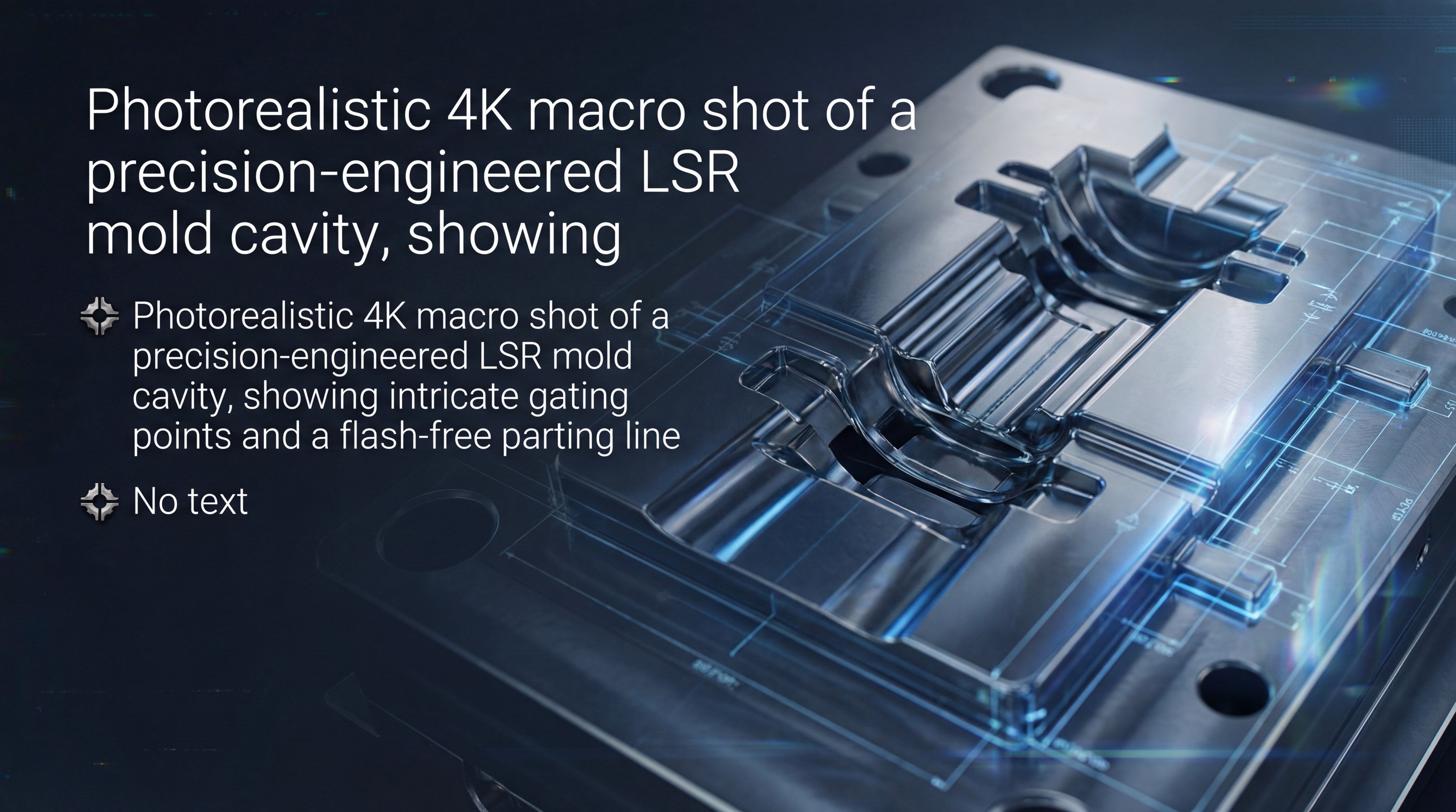
Critical tooling requirements focus on extreme precision and airtight seals to contain the low-viscosity liquid material before it cures. In the silicone injection molding environment, the “parting line” must be engineered to within microns to prevent flash from forming. You must also select a gating strategy that balances aesthetic requirements with the need for uniform pressure.
Flash-Free Tooling Design for Precision Seals
Because liquid silicone flows like water under pressure, any gap in the mold will lead to unsightly flash. High-quality molds are typically made from hardened steel and feature specialized venting to let air escape while keeping the silicone inside.
Best of all:
Precision gating ensures that the material enters the cavity smoothly, reducing the risk of air pockets or knit lines.
- Sub-gates for automatic degating
- Edge gates for visible parts
- Cold runner systems to reduce waste
- Vacuum venting for complex cavities
Gating Strategies for Minimal Aesthetic Impact
Gating locations should be placed in hidden or non-functional areas whenever possible to preserve the part’s finish. For high-volume production, cold runner systems are preferred because they keep the silicone in the distribution channels cold, preventing it from curing. This eliminates the “sprue” waste associated with traditional molding.
| Tooling Type | Material Waste | Setup Complexity | Production Speed |
|---|---|---|---|
| Cold Runner | Near Zero | High | Very Fast |
| Hot Runner | Low | High | Fast |
| Standard Sprue | High | Low | Moderate |
Proper gate placement is essential for ensuring that the last area to fill is properly vented, preventing “burn marks” from trapped air.
Key Takeaway: Precision tooling is mandatory to manage the low viscosity of liquid silicone and prevent flash.
7. How Does Automated Machinery Ensure Batch Consistency?
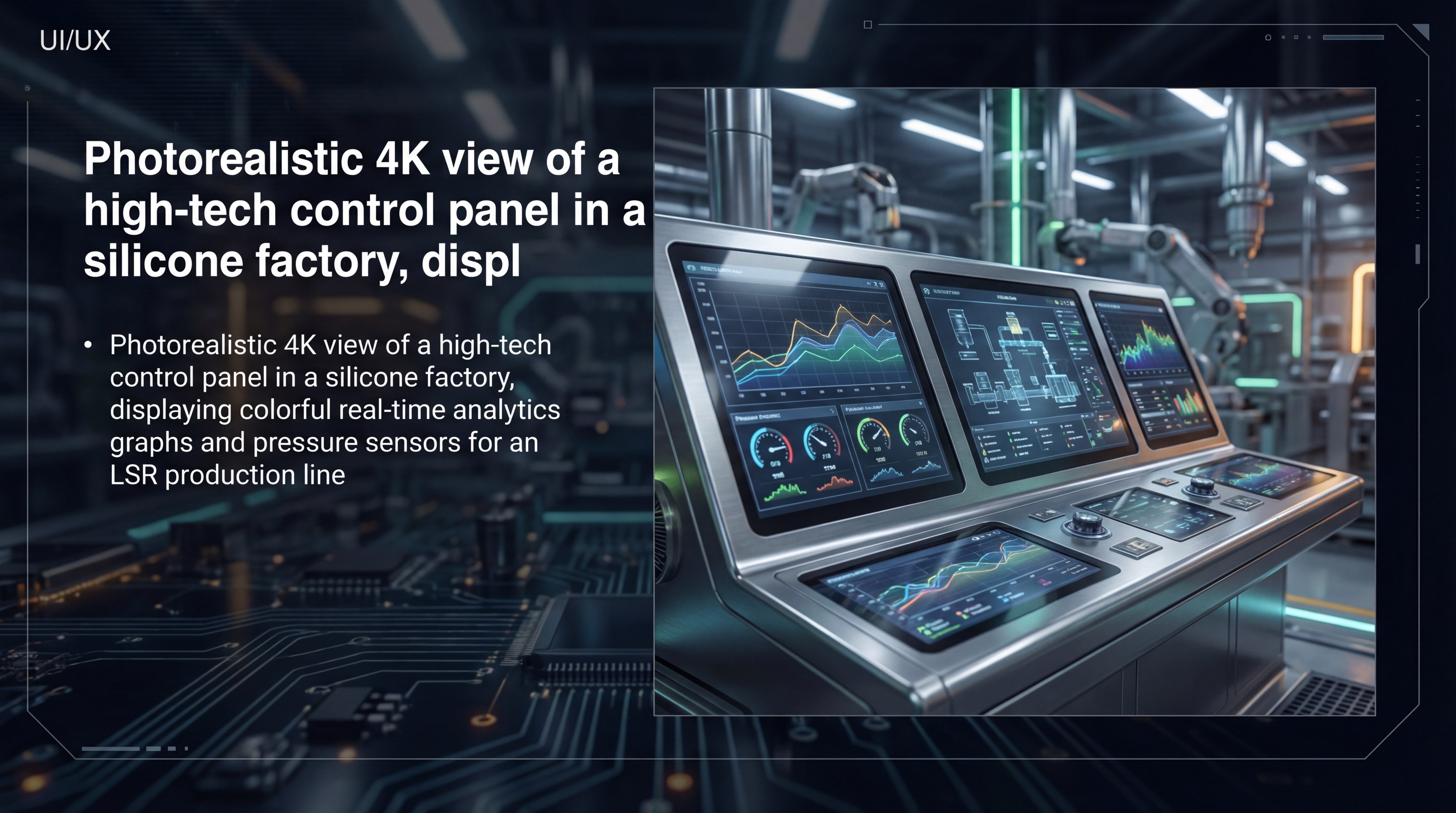
Automated machinery ensures consistency by monitoring every variable of the silicone injection molding process in real-time, from pressure to temperature. You will benefit from advanced sensors that detect even slight deviations in the 1:1 mixing ratio of Part A and Part B. This level of control guarantees that the physical properties of the silicone remain identical across millions of parts.
The Role of Metering Units in Chemical Stability
Metering units are responsible for delivering the exact volume of material required for each shot. If the ratio drifts even slightly, the silicone may under-cure or become brittle, leading to part failure.
That’s not all:
Modern machines use mass flow meters to confirm the weight of every shot, providing a digital paper trail for quality audits.
- Closed-loop injection control
- Real-time temperature feedback
- Automated A/B ratio correction
- Cycle-by-cycle data logging
Monitoring Pressure and Temperature for Quality
Maintaining a stable mold temperature is the most critical factor for ensuring a complete cure within the allotted cycle time. If the temperature drops, the part may be tacky; if it’s too high, the material may scorch. You can rely on automated alarm systems to stop the machine immediately if any parameter falls outside of the pre-set “tolerance window.”
| Parameter | Impact on Part | Monitoring Method |
|---|---|---|
| Injection Pressure | Density/Flash | Hydraulic Sensors |
| Mold Temp | Cure State | Thermocouples |
| Mix Ratio | Physical Integrity | Mass Flow Meters |
| Cycle Time | Throughput | PLC Timers |
The integration of smart sensors into the production line allows for “lights-out” manufacturing with zero sacrifice in part quality.
Key Takeaway: Automation reduces human error and ensures the 1:1 ratio of A and B components remains stable.
8. Why Is Prototyping Essential Before Full-Scale Production?
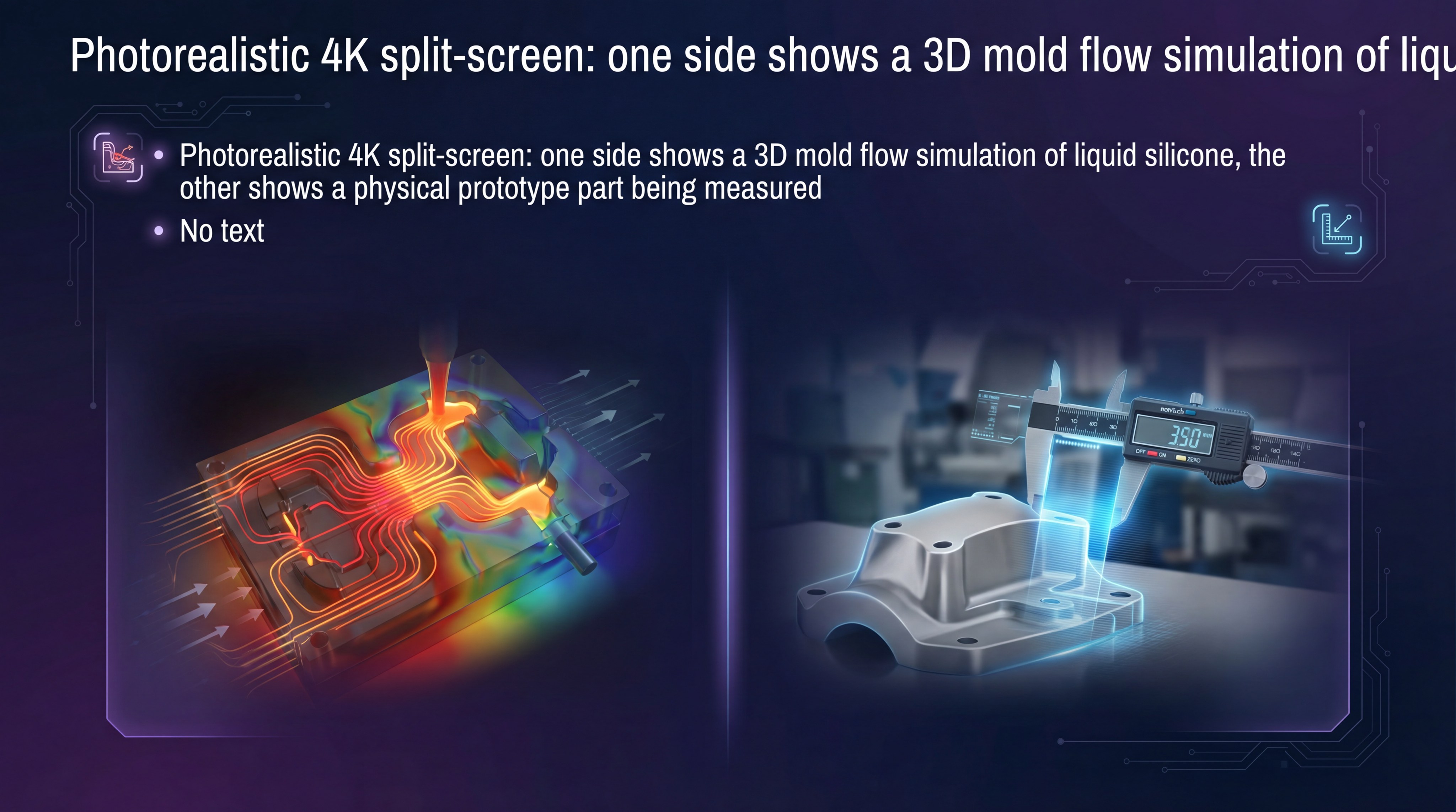
Prototyping is essential because it allows you to validate your design and material choice before committing to expensive multi-cavity production tooling. Through the silicone injection molding lens, a prototype tool can reveal potential flow issues or air traps that computer simulations might miss. You can use these early parts for functional testing and regulatory approvals.
Using DFM Reviews to Eliminate Design Risks
A Design for Manufacturing (DFM) review is the first step in the prototyping phase. Our engineers examine your CAD files to identify areas where wall thickness, draft angles, or gate locations could be improved.
In other words:
We find the problems on paper so they don’t become expensive mistakes in steel.
- Flow analysis simulations
- Draft and undercut verification
- Tolerance stack-up analysis
- Material compatibility checks
Functional Testing with CNC and 3D Printed Molds
For rapid iterations, we can use CNC-machined aluminum molds or even 3D-printed inserts to produce low-volume samples. While these tools aren’t meant for mass production, they provide parts that have the same physical properties as the final product. You can then perform real-world stress tests to ensure the design meets all performance requirements.
| Phase | Purpose | Tooling Type |
|---|---|---|
| Alpha | Form/Fit Check | 3D Printed / CNC |
| Beta | Functional Test | Single-Cavity Steel |
| Pilot | Process Validation | Multi-Cavity Pre-series |
Investing in a bridge tool or pilot run ensures that your final production launch is smooth, predictable, and free from design-related defects.
Key Takeaway: Pilot production runs allow for fine-tuning shrinkage rates before investing in multi-cavity mass production tools.
9. What Quality Standards Ensure Industry Compliance?
Quality standards ensure compliance by verifying that every part meets the rigorous mechanical and chemical specifications required by your industry. In silicone injection molding, this involves a combination of automated visual inspections and high-precision physical testing. You must ensure your partner follows a structured quality management system to maintain traceability for every batch.
Implementing IQC, IPQC, and FQC Systems
Quality control is divided into three main stages: Incoming, In-Process, and Final. We check the raw silicone material for purity before it ever reaches the machine.
The result?
A robust production pipeline where defects are caught at the source rather than at the end of the line.
- IQC: Raw material batch testing
- IPQC: First-article and hourly inspections
- FQC: 100% visual and dimensional checks
- OQC: Final packaging and documentation review
Dimensional Accuracy and Physical Property Testing
For critical seals and medical components, we use Coordinate Measuring Machines (CMM) to verify dimensions down to the micron. We also conduct “pull tests” to check tensile strength and “compression set” tests to ensure the material returns to its shape after long-term stress. You will receive a full Inspection Report (FAI) to confirm that the parts match your original drawings.
| Checkpoint | Measurement | Tooling |
|---|---|---|
| Dimensional | Length/Width/Bore | CMM / Video Mic |
| Hardness | Shore A Durometer | Durometer Gauge |
| Visual | Flash/Bubbles | CCD / Microscope |
| Reliability | Elongation/Tear | Tensile Tester |
These rigorous testing protocols are non-negotiable for industries where a single part failure could lead to a system-wide shutdown or safety risk.
Key Takeaway: Rigorous testing of tensile strength and compression set is vital for mission-critical parts.
10. How Can You Reduce Lead Times and Manufacturing Risks?
Reducing lead times requires integrating design, tooling, and production under one roof to eliminate communication gaps and shipping delays. By choosing a partner experienced in silicone injection molding, you ensure that the people building the mold are the same ones running the production line. This synergy allows for rapid troubleshooting and faster iterations during the development cycle.
Streamlining the Supply Chain with Integrated Services
When you use separate vendors for design, tooling, and molding, you risk “finger-pointing” if a part doesn’t meet specifications. An integrated factory takes full ownership of the process, from the first DFM review to final export.
Ready to get started?
Our team can guide you through the transition from a concept sketch to a fully realized, mass-produced component in record time.
- In-house mold design and fabrication
- Automated mass production lines
- Secondary operations (printing/coating)
- Global logistics and export support
Choosing the Right Manufacturing Partner
The right partner should offer more than just machine time; they should provide engineering expertise that adds value to your product. Look for certifications like ISO 9001 or IATF 16949 as proof of their commitment to operational excellence. You deserve a partner who views themselves as an extension of your own engineering team.
| Strategy | Integrated Workflow | Multi-Vendor Workflow |
|---|---|---|
| Communication | Single Point of Contact | Fragmented |
| Risk Level | Low (Internal Control) | High (Handoffs) |
| Speed | 4 – 6 Weeks | 8 – 12 Weeks |
| Accountability | 100% Factory Owned | Shared/Unclear |
By centralizing your production with a specialized silicone manufacturer, you minimize manufacturing risks and maximize your competitive advantage in the market.
Key Takeaway: Integrating design, tooling, and molding under one roof eliminates communication gaps and speeds up time-to-market.
*
Conclusion
At HuaLin Silicone, we are committed to transforming your complex designs into high-performance realities through precision engineering and advanced manufacturing. Our vision is to be the premier global partner for custom LSR solutions, providing unparalleled stability and quality for the medical, automotive, and electronics sectors. Whether you need a rapid prototype or a multi-million-part production run, our team is equipped to deliver results that exceed your expectations.
If you are looking for expert DFM advice or a competitive quotation for your next project, contact us today to speak with a silicone specialist.
*
FAQ: Common Questions About Silicone Injection Molding
- Can I use the same mold for different durometers of LSR?
- Answer: Generally yes, but shrinkage rates may vary slightly between hardness levels, which can affect the final tolerances of high-precision parts.
- What’s the best way to handle gates if appearance is critical?
- Answer: Use sub-gates or “hidden” edge gates placed on non-functional surfaces, and consider recessed gate locations that can be easily trimmed or concealed.
- Can I overmold silicone onto heat-sensitive plastics?
- Answer: It is challenging because LSR typically requires curing temperatures above 150°C; however, specialized low-temperature curing grades are available for such applications.
- What’s the best way to reduce the cost of an LSR project?
- Answer: Focus on DFM early to minimize tooling revisions and maximize the number of cavities in the mold for high-volume production runs.
- Can I achieve transparent parts with LSR?
- Answer: Yes, optically clear LSR grades are specifically designed for lighting, lenses, and medical applications where visual clarity is paramount.