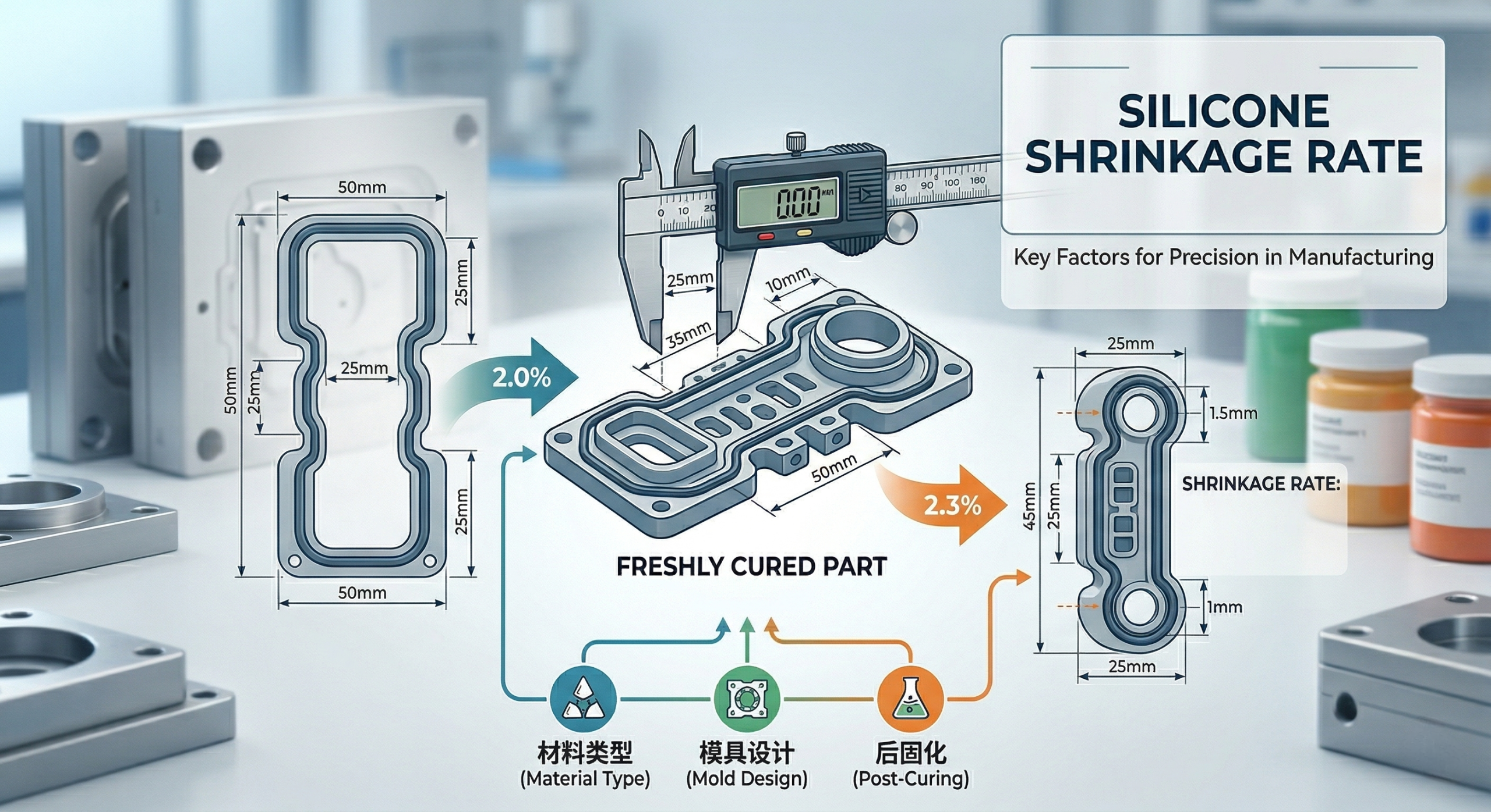
Mastering silicone shrinkage rates involves calculating the exact percentage of volume reduction that occurs during the curing process to ensure your final parts align with design specifications. Unpredictable dimensional variations in Silicone Products often lead to assembly failures and costly material waste. When your project requires high-precision seals or medical components, a deviation as small as 0.05mm can jeopardize the entire production run.
By implementing controlled manufacturing environments and advanced tooling strategies, you can mitigate these risks and achieve repeatable accuracy. We provide the technical expertise and high-performance manufacturing capabilities required to stabilize these complex variables. This ensures your project moves from prototype to mass production without the delays associated with dimensional non-compliance.
What Is Silicone Shrinkage Rate and Why Does It Matter?
The silicone shrinkage rate represents the physical contraction of the material as it transitions from a liquid or uncured state to a solid cured part. Accurately predicting this rate is the only way to ensure that your Silicone Products fit perfectly into their intended housings or assemblies.
The Science of Curing Contraction?
Curing contraction happens because the cross-linking of polymer chains pulls the molecules closer together, reducing the total volume. This phase is highly sensitive to the chemistry of the catalyst used in the mixture.
Think about this:
- Cross-linking density affects the pull of the molecules.
- Catalyst speed can increase or decrease local contraction.
- Cooling rates dictate how fast the material stabilizes.
Here is why: Controlling the molecular bond formation is the first step in ensuring your part doesn’t pull away from the mold edges prematurely.
Thermal Expansion vs. Chemical Shrinkage?
Chemical shrinkage occurs during the cross-linking phase, while thermal expansion happens when the heated part is removed from the tool and cools. You must calculate both to determine the final “oversize” needed for the mold cavity.
The result?
- Chemical shrinkage is usually a fixed percentage of the material.
- Thermal contraction depends on the temperature delta between the mold and the environment.
- Complex geometries may shrink unevenly across different axes.
But that’s not all.
Key Takeaway: Dimensional accuracy relies on a dual-calculation of chemical and thermal shrinkage to prevent out-of-spec parts.
| Shrinkage Type | Primary Cause | Impact on Part |
|---|---|---|
| Chemical | Molecular Cross-linking | Permanent volume reduction |
| Thermal | Temperature Differential | Dimensional contraction upon cooling |
Accurate mold design must compensate for both chemical and thermal factors to achieve the target tolerances.
Which Factors Impact the Overall Silicone Shrinkage Rate?
Material hardness, filler content, and injection parameters are the primary variables that dictate the final size of your Silicone Products after they leave the factory-direct production line. If you change even one material additive, the shrinkage coefficient will shift significantly.
Material Hardness and Filler Content?
Softer silicone grades generally exhibit higher shrinkage rates than harder grades because they contain fewer reinforcing fillers. These fillers take up space and do not contract during the curing cycle.
Simply put:
- 30 Shore A materials shrink more than 70 Shore A materials.
- Silica fillers act as stabilizing agents within the matrix.
- High filler content reduces the overall “active” polymer volume.
Here is why: You must select your material durometer early in the design phase to avoid remaking expensive steel tooling.
Injection Pressure and Temperature?
Higher injection pressures can “pack” more material into the mold, which counteracts some of the natural shrinkage that occurs during cooling. Temperature also plays a role by determining the expansion of the material before it sets.
But there is more.
- High pressure minimizes the gap between the part and the mold wall.
- Mold temperature must be uniform to prevent localized shrinkage.
- Variations in cycle time can cause batch-to-batch inconsistency.
The goal is to maintain a stable, repeatable environment for every shot.
Part Wall Thickness Variability?
Thicker sections of a part retain heat longer and shrink more than thinner walls, often leading to internal voids or surface sink marks. Maintaining uniform wall thickness is critical for dimensional stability.
Consider this:
- Thicker walls create uneven cooling profiles.
- Transition zones between thick and thin areas are prone to warping.
- Ribs and bosses should be sized relative to the main wall.
Here is why: Designing for uniform wall thickness is the most effective way to prevent internal stresses from distorting your final product.
Key Takeaway: Balancing material hardness and wall thickness allows for a predictable and controllable shrinkage environment.
| Variable | Increase in Variable | Effect on Shrinkage |
|---|---|---|
| Durometer (Hardness) | Increase | Shrinkage Decreases |
| Injection Pressure | Increase | Shrinkage Decreases |
| Wall Thickness | Increase | Shrinkage Increases |
Managing these three variables simultaneously ensures that your high-volume production remains within specified tolerances.
How Does Material Selection Affect Final Dimensions?
Choosing between Liquid Silicone Rubber (LSR) and High Consistency Rubber (HCR) fundamentally changes how you calculate shrinkage for your Silicone Products. Each material class has unique rheological properties that influence how it fills the cavity and settles during cooling.
LSR vs. High Consistency Rubber (HCR)?
LSR typically has a higher shrinkage rate than HCR because it is processed at lower viscosities and higher injection pressures. This makes it ideal for complex, small parts where precision is paramount despite the higher contraction.
Here is the truth:
- LSR shrinkage usually ranges between 2.0% and 3.5%.
- HCR shrinkage is often lower, ranging from 1.0% to 2.5%.
- Platinum-cured systems provide better stability than peroxide systems.
The result? Your tooling must be specifically designed for the exact material grade you choose to use.
Specialty Grades for Medical and Food Safety?
Medical and food-grade silicones often require platinum catalysts, which offer cleaner curing but different shrinkage profiles compared to industrial-grade silicones. These medical-grade silicone parts must undergo rigorous validation to ensure they meet strict regulatory dimensions.
Check this out:
- Platinum curing produces no volatile by-products.
- Biocompatibility requirements may limit the use of certain fillers.
- Post-curing is often mandatory, adding another layer of shrinkage.
But that’s not all.
Low-Shrinkage Compounds for High Precision?
For applications where tolerances are exceptionally tight, manufacturers develop custom compounds with specific additives designed to minimize volume loss. These materials are essential for aerospace and high-end electronics.
Here is why:
- Proprietary fillers can reduce shrinkage to below 1%.
- Stable polymers ensure consistency across thousands of cycles.
- Lower shrinkage reduces the risk of part warping.
Simply put: When “standard” isn’t enough, custom material engineering is the answer.
Key Takeaway: Material chemistry, specifically the catalyst and filler type, is the leading predictor of how much a part will contract.
| Material Type | Curing System | Typical Shrinkage |
|---|---|---|
| LSR | Platinum | 2.5% – 3.5% |
| HCR | Peroxide | 1.5% – 2.0% |
| HCR | Platinum | 1.2% – 1.8% |
Selecting the right material grade at the start prevents the need for costly mold modifications later in the project.
What Is the Role of the Curing Process in Shrinkage Control?
The curing process is the “moment of truth” where temperature and time determine the final physical properties and size of your Silicone Products. At our ISO-certified facility, we use precise control systems to monitor these thermal cycles in real-time.
Optimal Temperature Profiles?
If the mold temperature is too high, the material expands excessively before curing, leading to massive shrinkage once it cools down to room temperature. Conversely, low temperatures can lead to under-curing and dimensional instability.
The result?
- Uniform heating across the mold face is mandatory.
- Multi-zone heating allows for compensation in complex tools.
- Rapid heating can cause “skinning,” where the outside cures faster than the inside.
Here is why: A balanced thermal profile ensures the material cross-links evenly throughout the entire part geometry.
Curing Time and Cross-linking Density?
Shortening the cycle time to save costs can lead to incomplete cross-linking, which results in a part that continues to shrink or deform after it is ejected. You must allow enough time for the molecular structure to fully stabilize.
But there’s more.
- Longer cycles generally produce more stable parts.
- Over-curing can lead to brittleness and reduced elasticity.
- Secondary curing stages are often required for final stability.
Simply put: Speed should never come at the expense of structural integrity.
Pressure Distribution in the Mold?
Uneven pressure within the mold cavity causes different areas of the part to shrink at different rates, leading to warping. This is particularly problematic in multi-cavity tools where flow must be perfectly balanced.
Think about this:
- Gate location determines the pressure gradient.
- Venting allows air to escape so the material can pack fully.
- Consistent clamping force prevents flashing and dimensional drift.
The goal is to achieve a uniform density across the entire part.
Key Takeaway: Precise control over temperature and pressure during the curing cycle is non-negotiable for high-precision manufacturing.
| Curing Factor | Under-Condition | Over-Condition |
|---|---|---|
| Temperature | Incomplete cure / Softness | Brittleness / High Shrinkage |
| Time | Dimensional Instability | Scorching / Material Degradation |
| Pressure | Voids / High Shrinkage | Flash / Mold Damage |
Stability in the curing cycle translates directly to stability in your final product dimensions.
How Does Mold Design and Part Geometry Minimize Deviations?
Smart mold design is your best defense against the natural physical limitations of silicone materials. By using custom LSR communication parts as a benchmark, we design tools that compensate for shrinkage in the most critical functional areas.
Strategic Gate Placement?
The gate is where material enters the mold, and the area near the gate typically experiences the highest pressure and the lowest shrinkage. Placing gates strategically ensures that critical dimensions are shielded from excessive contraction.
Consider this:
- Center gating is best for symmetrical parts like O-rings.
- Edge gating is common for flat, thin components.
- Sub-gates allow for automatic de-gating during ejection.
Here is why: Your choice of gate location dictates the flow front and the final stress distribution of the part.
Draft Angles and Undercuts?
Proper draft angles allow the part to be ejected without stretching or tearing, which could permanently distort the dimensions. If a part “hangs” in the mold, it may cool unevenly and shrink into an oval or warped shape.
The result?
- 1 to 2 degrees of draft is standard for silicone.
- Textured surfaces require higher draft angles.
- Undercuts should be avoided or managed with collapsible cores.
But that’s not all.
Uniform Wall Thickness Principles?
Parts with significant transitions in thickness will always experience internal stress as the thin areas cool faster than the thick ones. Designing for uniformity is the gold standard for high-precision silicone engineering.
Simply put:
- Keep wall transitions gradual.
- Use fillets to reduce stress concentrations at corners.
- Hollow out thick sections while using ribs for strength.
The result? A part that shrinks uniformly and remains true to its CAD model.
Key Takeaway: Strategic mold geometry and gate placement are essential for counteracting non-uniform material shrinkage.
| Design Element | Recommended Strategy | Benefit |
|---|---|---|
| Gate Location | Near critical dimensions | Higher pressure, lower shrinkage |
| Draft Angle | 1.5° minimum | Easier ejection, no distortion |
| Wall Thickness | 2mm – 4mm (Uniform) | Stable cooling and even shrinkage |
Proactive design choices significantly reduce the risk of warping and dimensional rejection.
Why Is Precision Tooling Design Crucial for Silicone Products?
Precision tooling is the physical foundation upon which all Silicone Products are built. Because silicone shrinks, the mold cavity must be machined “oversize” using a specific shrinkage factor tailored to your material and process.
In-House Mold Making Advantages?
Having in-house mold design and manufacturing allows for faster iterations and tighter control over the tolerances of the tool itself. When you work with an integrated partner, the engineers who design the part are the ones building the tool.
Check this out:
- Direct communication reduces translation errors.
- Tooling can be adjusted quickly after the first articles are tested.
- Integrated DFM reviews happen before any steel is cut.
Here is why: In-house tooling eliminates the “supplier gap” that often leads to delays and quality drift.
Compensating for Shrinkage in CAD?
Modern CAD software allows engineers to apply non-uniform scaling to account for the fact that silicone doesn’t always shrink the same amount in all directions. This is particularly important for overmolded parts where silicone is bonded to plastic or metal.
But there is more.
- 3D flow analysis predicts how the material will behave.
- Shrinkage factors are applied to the tool, not the part.
- Precision CNC machining ensures the tool matches the CAD data.
Simply put: Digital simulation is the key to getting it right the first time.
Steel Selection for High-Volume Tooling?
The type of steel used for the mold impacts how well it retains heat and how long it lasts under the high pressures of LSR injection. High-grade stainless steel is preferred for its thermal stability and corrosion resistance.
Think about this:
- S136 or H13 steel is common for precision molds.
- Hardened steel prevents wear on shut-off surfaces.
- Proper polishing reduces friction during ejection.
Here is why: A high-quality tool produces consistent parts from the first shot to the millionth.
Key Takeaway: Precision tooling, built with integrated DFM, is the only way to reliably manage the complex physics of silicone shrinkage.
| Tooling Aspect | Target Standard | Impact on Precision |
|---|---|---|
| Cavity Tolerance | ±0.01mm | Foundation for part accuracy |
| Surface Finish | SPI-A2 (Mirror) | Reduces ejection stress |
| Cooling Channels | Conformal / Balanced | Ensures uniform part shrinkage |
Investing in high-quality tooling is the most cost-effective way to ensure long-term production stability.
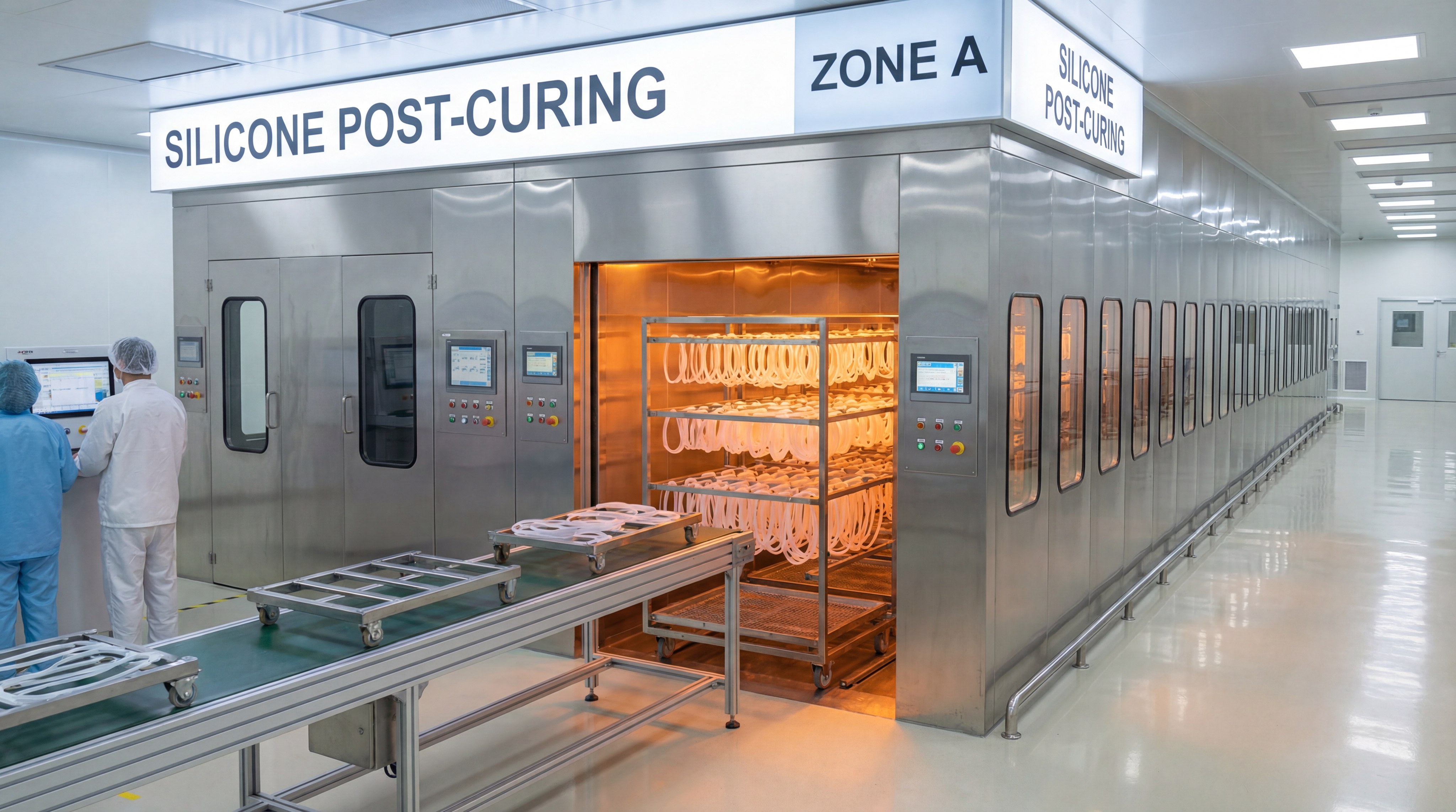
How Does Post-Curing Impact the Performance of Silicone Products?
Post-curing involves heating your Silicone Products in a secondary oven after they have been molded. This process is essential for baby care products and medical devices to ensure they are safe, stable, and durable.
Eliminating Volatile Components?
Standard molding can leave behind small amounts of catalysts or volatile organic compounds (VOCs). Post-curing “bakes” these out, ensuring the silicone is chemically inert and safe for human contact.
Here is the truth:
- Volatiles can cause odors or surface blooming.
- Removing VOCs is mandatory for FDA and LFGB compliance.
- Post-curing stabilizes the material’s final odor profile.
The result? A cleaner, safer product for the end consumer.
Achieving Final Dimensional Stability?
During post-curing, the material completes its final stage of shrinkage. If you do not post-cure a part that requires it, the part may continue to shrink over time while in storage or in the hands of your customer.
But that’s not all.
- Post-curing shrinkage can be as high as 0.5%.
- It “relaxes” internal stresses created during injection.
- It ensures the part stays the same size for its entire lifecycle.
Simply put: Post-curing is the final step in “locking in” the part’s dimensions.
Enhancing Physical Properties?
Beyond size, post-curing improves the compression set, tensile strength, and heat resistance of the silicone. This makes the material more resilient in demanding industrial environments.
Consider this:
- Compression set improves by up to 50%.
- Tensile strength becomes more consistent.
- The material becomes more resistant to permanent deformation.
Here is why: If your part needs to maintain a seal under load, post-curing is a non-negotiable requirement.
Key Takeaway: Post-curing is essential for achieving chemical purity and long-term dimensional stability in high-performance silicone.
| Post-Cure Metric | Before Post-Cure | After Post-Cure |
|---|---|---|
| Volatile Content | Higher (VOCs present) | Minimal (Inert) |
| Compression Set | Poor | Excellent |
| Dimension | Intermediate | Final / Stable |
Failure to post-cure can lead to “delayed shrinkage,” causing assembly failures weeks after the parts leave the factory.
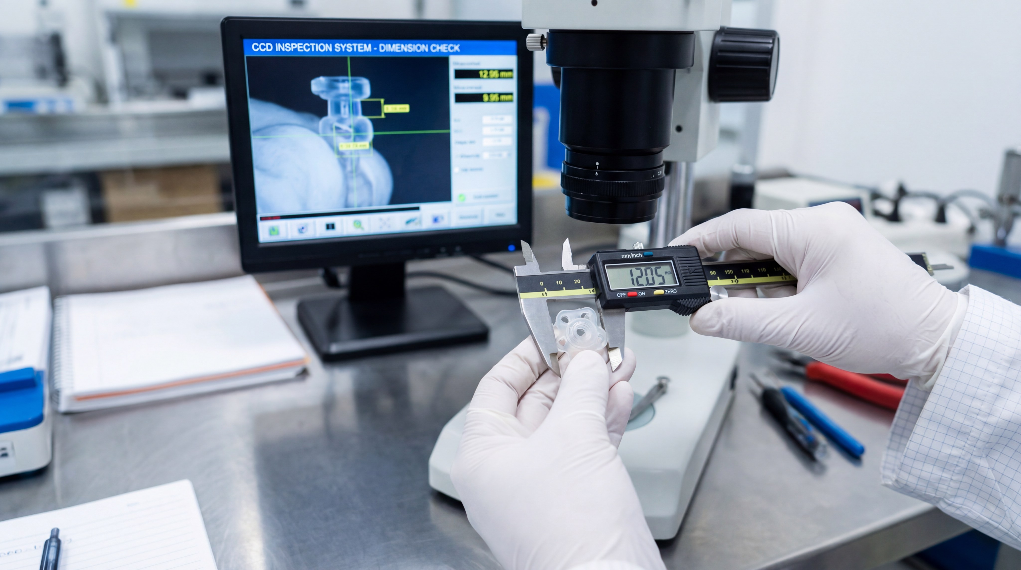
What Quality Testing Methods Verify Dimensional Accuracy?
Verifying the dimensional accuracy of Silicone Products requires specialized equipment because the material is flexible. Standard contact measurements like calipers can “squish” the part, leading to false readings.
CCD Visual Inspection Systems?
Automated CCD cameras take high-resolution images of the part and compare them to the CAD model without ever touching the material. This is the fastest and most accurate way to inspect 100% of a production batch.
Check this out:
- Non-contact measurement avoids part distortion.
- Sub-pixel accuracy detects tiny flash or defects.
- Inspection data is logged for full traceability.
Here is why: High-speed visual inspection is the only way to maintain quality at the speeds required for mass production.
Automated Dimensional Measurement?
For 3D features, we use automated coordinate measuring machines (CMMs) equipped with laser or optical probes. This allows us to verify complex geometries and internal features with extreme precision.
But there is more.
- Laser scanning creates a complete “cloud” of the part.
- Instant feedback allows operators to adjust machines.
- Automated reports provide the documentation needed for audits.
Simply put: Data-driven inspection removes the element of human error from the quality process.
Environmental Stress Testing?
To ensure the part remains within spec under real-world conditions, we subject it to extreme temperatures and chemicals. This confirms that the shrinkage and expansion won’t cause the part to fail in the field.
Think about this:
- Thermal aging tests simulate years of use.
- Chemical resistance checks for material swelling.
- Compression tests verify sealing performance over time.
The result? You can be confident that your product will perform as designed for its entire lifespan.
Key Takeaway: Non-contact measurement and environmental testing are critical for validating the precision of flexible silicone components.
| Testing Method | Best For | Advantage |
|---|---|---|
| CCD Vision | High-volume surface checks | 100% inspection, non-contact |
| Optical CMM | Complex 3D dimensions | Highly accurate, no part squish |
| Thermal Aging | Long-term reliability | Predicts future shrinkage/failure |
Integrated quality control ensures that only parts meeting 100% of your specifications reach your warehouse.
How Can Manufacturers Ensure Optimal Silicone Product Manufacturing?
Optimizing the manufacturing of Silicone Products requires an integrated approach that connects design, tooling, and mass production under one roof. When you contact us for a review, our engineering team looks at the entire lifecycle of the part.
Integrated DFM (Design for Manufacturing)?
Design for Manufacturing (DFM) is the process of optimizing your part’s geometry to be as “mold-friendly” as possible. This reduces cycle times, minimizes scrap, and ensures that shrinkage is predictable.
Simply put:
- We identify thick sections that might cause sink marks.
- We suggest gate locations that won’t leave ugly marks.
- We help you choose a material that balances cost and precision.
Here is why: Small changes at the design stage can save tens of thousands of dollars in production costs.
Real-Time Process Monitoring?
Modern injection molding machines are equipped with sensors that monitor pressure, temperature, and flow speed in real-time. If any variable drifts out of the “green zone,” the machine can automatically divert the suspect part to a scrap bin.
Check this out:
- Digital twins simulate the process before it starts.
- Sensors detect tiny changes in material viscosity.
- Closed-loop control adjusts parameters on the fly.
But that’s not all.
Closed-Loop Quality Control?
By feeding inspection data back into the production system, we can proactively adjust the molding parameters to stay ahead of any dimensional drift. This creates a “self-correcting” factory environment.
The result?
- Near-zero scrap rates.
- Perfect consistency between production runs.
- Reduced lead times for re-orders.
Here is why: Precision is not an accident; it is the result of a controlled, data-driven system.
Key Takeaway: Success in silicone manufacturing is achieved through early-stage DFM and continuous, real-time process monitoring.
| Optimization Step | Who Benefits | Result |
|---|---|---|
| DFM Review | Designers | Fewer tooling revisions |
| Process Monitoring | QC Team | Lower scrap and higher yield |
| Closed-Loop Data | Factory Manager | Maximum efficiency and consistency |
A holistic approach to manufacturing protects your project from the “hidden costs” of poor quality control.
How Should Designers Plan for Tolerances in Silicone Products?
Tolerancing for Silicone Products is different than tolerancing for steel or plastic. Because silicone is elastic and has a high thermal expansion coefficient, expecting “machined steel” tolerances is often unrealistic and unnecessarily expensive.
Standard ISO 3302-1 Classifications?
The industry standard for silicone tolerances is ISO 3302-1, which divides tolerances into classes like M1 (Fine), M2 (High Quality), and M3 (Standard). Most precision silicone parts aim for M1 or M2.
Think about this:
- M1 is typically used for high-precision medical seals.
- M2 is the standard for most consumer and industrial goods.
- M3 is used for non-critical, large gaskets.
Here is why: Selecting the right tolerance class ensures you aren’t paying for “over-engineering” where it isn’t needed.
Collaboration with the Tooling Team?
Your tolerance requirements should be discussed with the tooling engineers before the mold is finalized. They can tell you if a specific dimension is achievable given the material’s shrinkage rate and part geometry.
But there is more.
- Tooling can “favor” one side of a tolerance.
- “Steel safe” areas can be left for final adjustment.
- Prototype molds can verify shrinkage before mass tooling.
Simply put: Clear communication prevents impossible expectations.
Risk Assessment for Tight Tolerances?
If you require tolerances tighter than M1, you must be prepared for higher scrap rates and more frequent mold maintenance. These “hyper-precision” projects require the highest level of process control.
The result?
- Specialized measurement equipment is required.
- Environmental controls must be strictly enforced.
- Material batches must be perfectly consistent.
But that’s not all.
Key Takeaway: Use ISO 3302-1 as your guide and collaborate early with your manufacturer to set realistic, functional tolerances.
| Tolerance Class | Difficulty | Typical Application |
|---|---|---|
| ISO 3302-1 M1 | High | Medical Implants / Micro-seals |
| ISO 3302-1 M2 | Medium | Wearables / Telecom Insulators |
| ISO 3302-1 M3 | Low | Protective Boots / Bumpers |
Aligning your design tolerances with manufacturing realities is the final step in a successful precision project.
FAQ
Can I adjust the shrinkage rate after the mold is already built?
Adjusting parameters like injection pressure or mold temperature can provide minor dimensional corrections, but significant changes usually require machining the mold or changing to a different material grade with a similar shrinkage coefficient.
What’s the best way to calculate shrinkage for LSR vs. Compression molding?
LSR typically has a higher and more complex shrinkage rate (approx. 2-3.5%) compared to compression molding; the best method is to use specialized DFM software and refer to the specific material data sheet provided by the supplier.
How do I know if my silicone product requires post-curing?
If your part is intended for medical, baby care, or high-load industrial sealing applications, post-curing is generally necessary to ensure chemical safety (VOC removal) and long-term dimensional stability.
Can I use the same mold for different silicone grades?
Rarely. Since different grades have unique shrinkage coefficients—for instance, a mold designed for 40 Shore A will produce out-of-spec parts if injected with a 70 Shore A material—you must usually build a specific tool for each material.
What’s the best material for low-shrinkage medical applications?
Platinum-cured liquid silicone rubber (LSR) is the industry gold standard for medical applications because it offers high dimensional precision, biocompatibility, and consistent performance across massive production volumes.
Mastering Dimensional Excellence in Silicone
Achieving precision in silicone manufacturing requires a deep understanding of material science, thermodynamics, and high-level tooling design. By controlling the variables that lead to shrinkage—from material selection to post-curing—you ensure that your products perform reliably in the most demanding environments.
At HuaLin Silicone, our vision is to simplify the complex journey from concept to mass production for global OEM/ODM partners. We invite you to contact us today to discuss your precision requirements. Let our engineering team provide the DFM support and controlled manufacturing environment your next project deserves. Together, we can build stable, high-quality silicone solutions that exceed expectations and drive your brand forward.